
An RP2350 Gives Vintage PC Video a Route to a Modern Screen
Published October 11, 2026
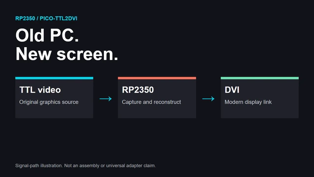
Conceptual data path, not a tested wiring guide or a photograph of a completed adapter.
pico-ttl2dvi samples legacy digital video and reconstructs it for DVI output. The interesting work is timing, not just finding an adapter plug.
The old computer still works. The monitor is the problem.
That is a good reason to look at pico-ttl2dvi, an actively developed RP2350 project by charlysan. It captures digital TTL video from vintage graphics hardware, reconstructs a framebuffer, and emits DVI through PicoDVI. Its documented sources include MDA/Hercules, CGA, EGA, and Commodore 128 VDC modes. The source was updated inside the October research window; this is not a claim that every supported mode arrived this week. Project documentation.
The conversion sounds simple until the word "timing" enters the room. The incoming source and outgoing display do not become compatible merely because a connector can be attached to each end.
TTL Is Not Analog VGA
The first job is identifying the signal. A legacy digital interface is not interchangeable with analog VGA because both happen to produce a picture. The data lines, voltage levels, clock assumptions, and synchronization need to match the actual source.
The repository documents its supported signal layouts and distinguishes modes within the same graphics family. That matters when an interface changes what a pin means between configurations. An adapter should be selected from the signal specification, not from a photograph of a vaguely similar socket.
This article is not a replacement for the current wiring documentation. Check the exact board profile, source mode, level handling, and ground connection before connecting valuable hardware. A resistor-only shortcut copied out of context is a poor way to protect an old graphics card.
Capture and Display Are Separate Problems
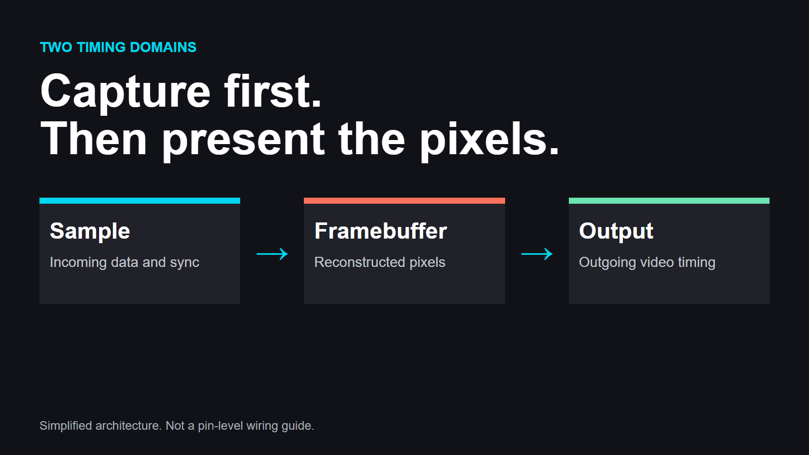
The RP2350's programmable I/O samples the incoming signal. Reconstruction turns that sampled data into pixels in a framebuffer. Output generation then presents those pixels on a different video link.
The framebuffer is the bridge. It lets the system connect the source's raster behavior to an output raster without assuming the two sides are one continuous wire. That also creates decisions about framing, scaling, and which data is accepted as a stable source.
A wrong sampling phase can produce a picture that is almost right: text shimmers, edges repeat, or stripes appear. Those symptoms are more useful than the vague conclusion that "HDMI conversion is bad." They point toward a capture-timing question that can be tested.
The documentation describes tuning controls and automatic source detection. Automatic behavior remains subject to the supported modes and measured conditions. It should not be expanded into a promise that any nine-pin video output will be recognized.
Give Yourself a Known Picture
For troubleshooting, begin with a source pattern whose structure you know. High-contrast text or a test pattern is easier to evaluate than a busy game scene. Keep the source configuration fixed while changing one timing parameter.
An output display can introduce another layer of processing. Scaling and display settings may change how the same captured pixels look. Before attributing an artifact to the vintage machine, distinguish what was captured from how the modern screen presents it.
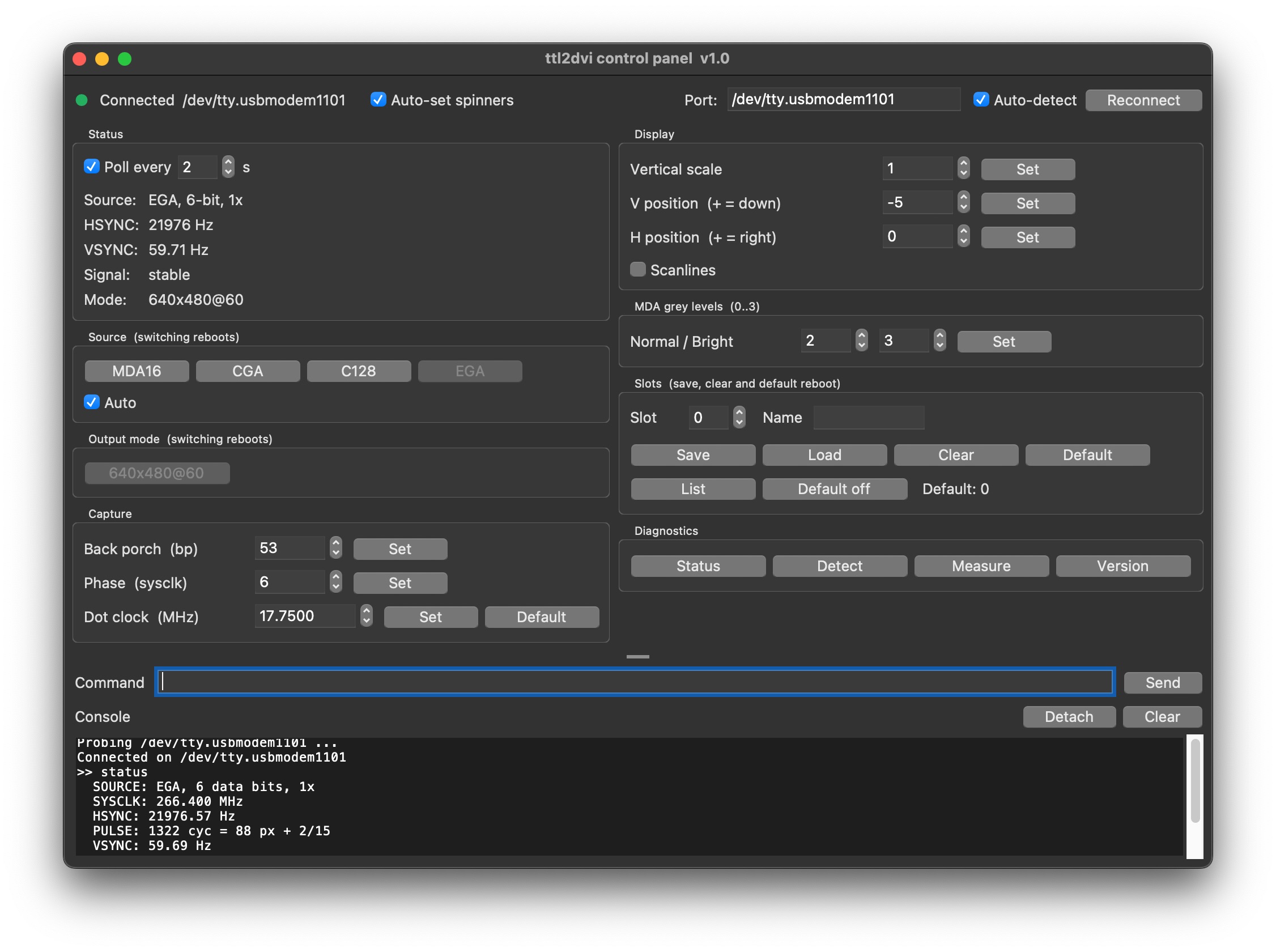
Saving a configuration is useful only if the record describes what it was tuned for. Include the graphics card, mode, board profile, and firmware revision. A setting that works for one source can become a misleading default for a different oscillator or raster.
Open Firmware Makes the Boundary Inspectable
The repository lays out capture, video generation, settings, console tools, and board configuration. It also acknowledges PicoDVI and keeps the vendored component's license. That gives readers a route to inspect the boundary between the incoming legacy signal and the outgoing display.
The benefit is not a guarantee that every setup works on the first attempt. It is that a failure can become a specific question: detection, sampling phase, reconstruction, framing, or output mode.
That is the appeal of this kind of preservation project. The old machine does not have to be replaced by an emulator to become viewable again. A small modern processor can serve as an interpreter at the interface, while the original computer remains responsible for generating the picture.
If your vintage system needs a new display route, what is its actual video standard? Add the machine and the troublesome symptom in the comments below.
Source and original creator: charlysan's pico-ttl2dvi. This is an explanatory article, not a claim that we assembled or verified the adapter.
Comments
Member comments are temporarily unavailable.
Log in to join the discussion.