Build JPL's Six-Wheel Open Source Rover
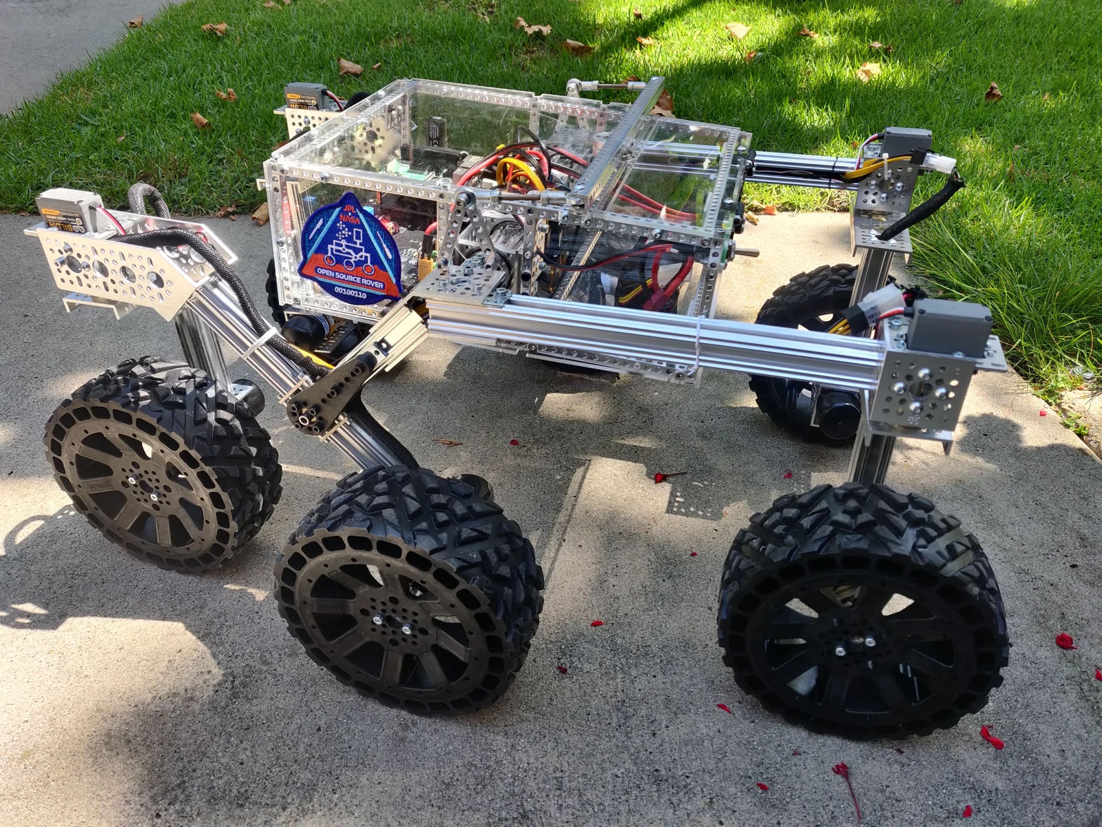
Photo credit
images/osr-side-outside.jpg
JPL / California Institute of Technology and Open Source Rover contributors · Apache-2.0Resized without cropping and converted to WebP.
Before you build
A substantial robotics build rather than a quick desktop toy. The original team estimates at least 100 person-hours and describes mechanical, electronics, and software skills. This page includes all reviewed hardware build chapters in roadmap order, with the original assembly figures, parts tables, and circuit schematic PDF. Software setup remains linked to the team's separate rover-code repository; CAD and firmware downloads keep their source links. The original budget and performance estimates describe the source design, not current quotes or independent testing. Respect the battery, electrical, and fabrication warnings. No NASA, JPL, or Caltech endorsement of this republication is implied.
The complete reviewed JPL rover hardware manual: parts lists, wiring, PCB assembly, mechanical chapters, original build photographs and diagrams, optional mast, and downloadable schematics.
JPL Open Source Rover Project
NOTE: For the previous major version of the OSR, please see v3.1.0.
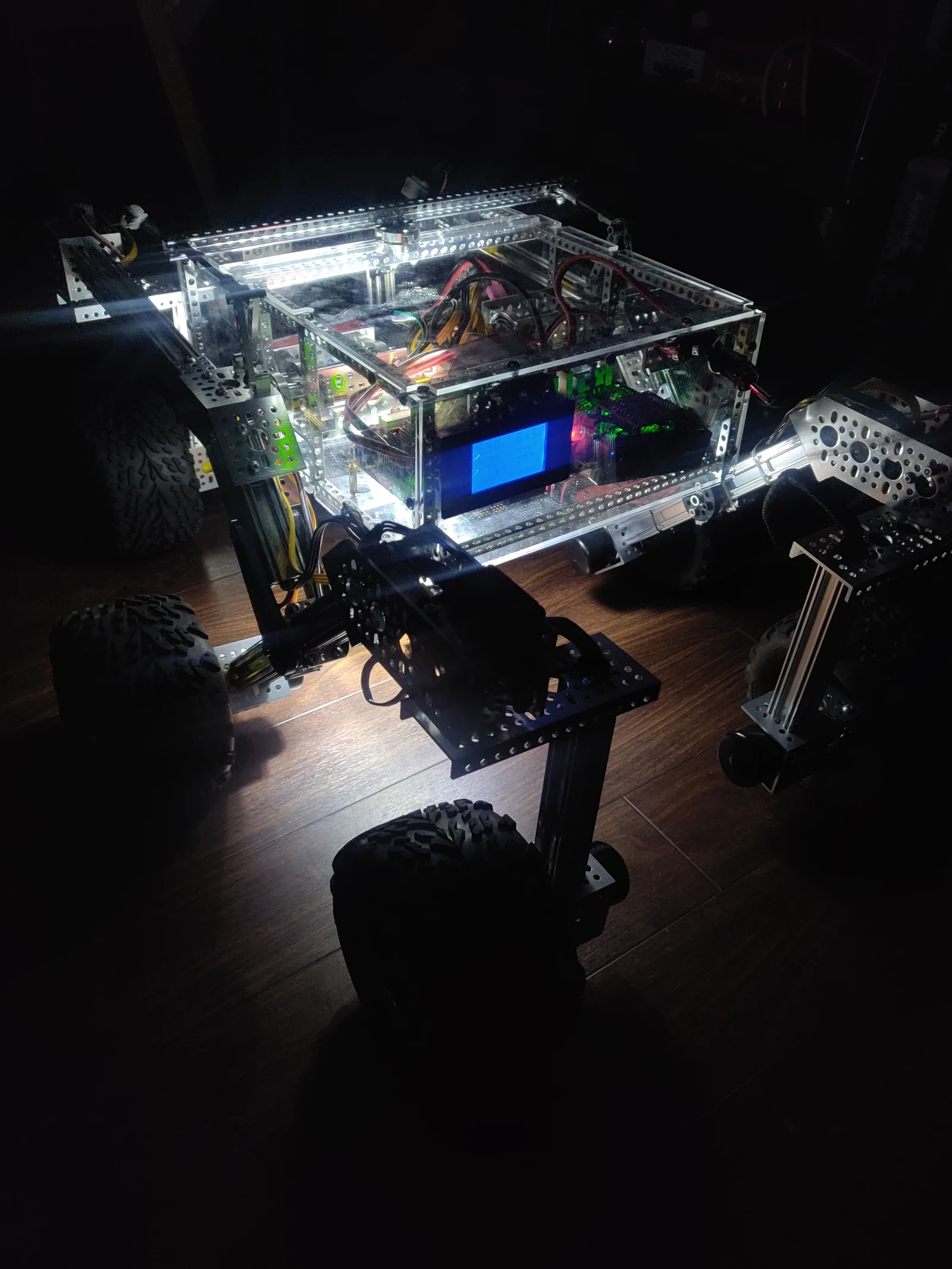 Photo creditimages/lit_up_shot.jpg JPL / California Institute of Technology and Open Source Rover contributors · Apache-2.0Resized without cropping and converted to WebP. | Photo creditimages/osr-side-outside.jpg JPL / California Institute of Technology and Open Source Rover contributors · Apache-2.0Resized without cropping and converted to WebP. |
|---|---|
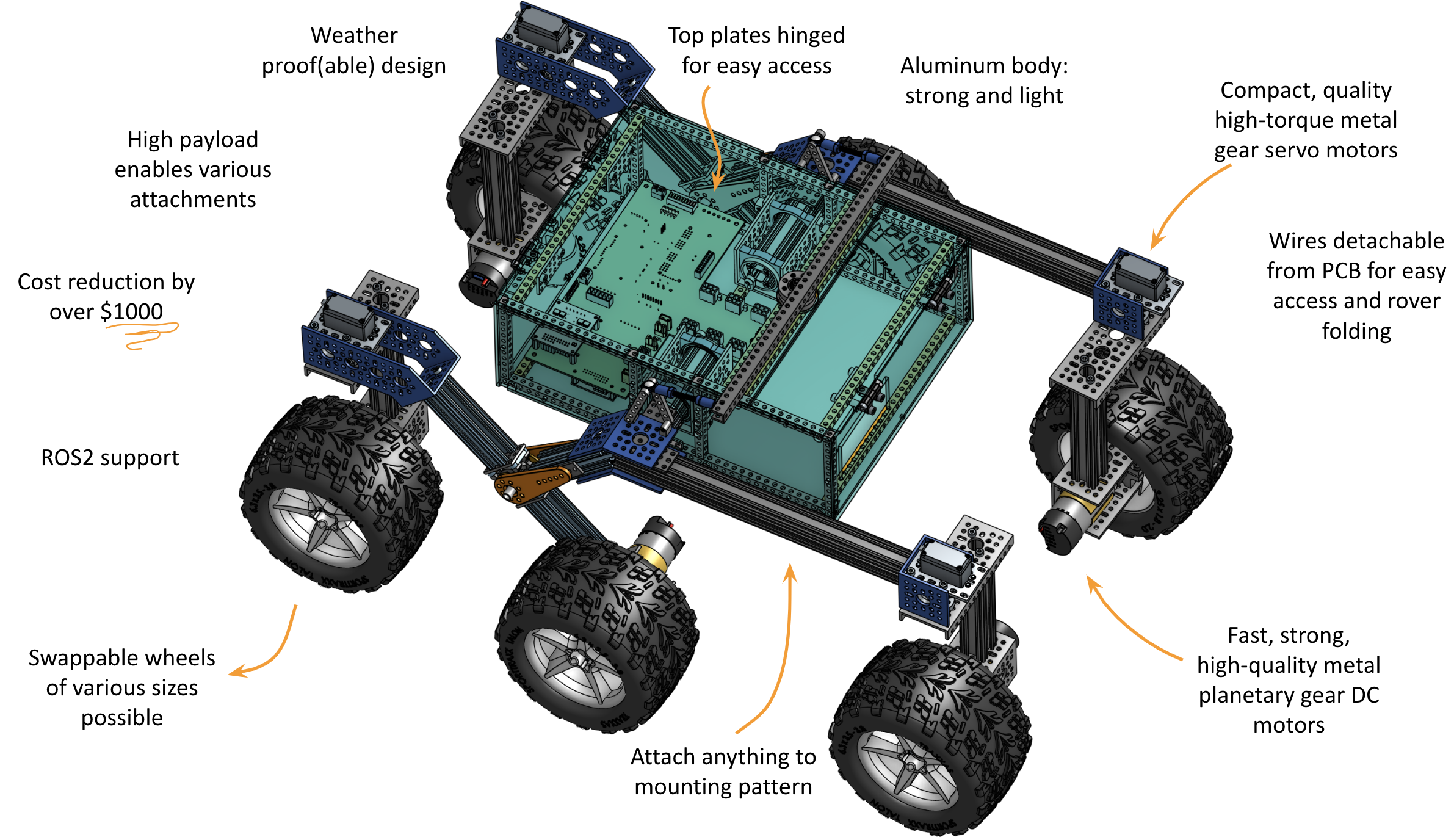 Photo creditimages/rover.png JPL / California Institute of Technology and Open Source Rover contributors · Apache-2.0Unmodified source image. | 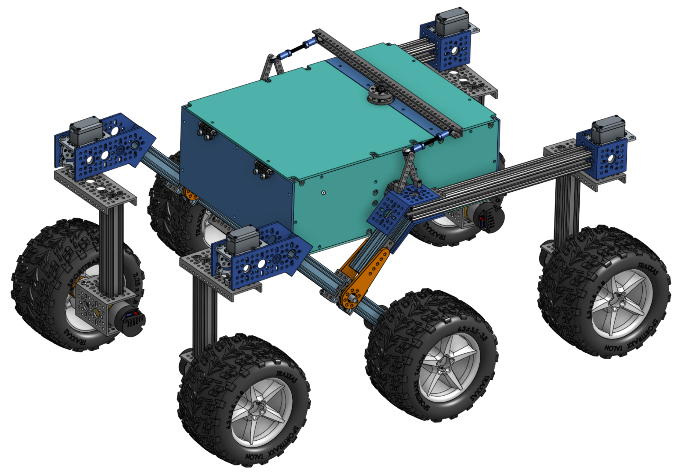 Photo creditimages/osr_onshape.png JPL / California Institute of Technology and Open Source Rover contributors · Apache-2.0Unmodified source image. |
The JPL Open Source Rover is an open source, build it yourself, scaled down version of the 6 wheel rover design that JPL uses to explore the surface of Mars. The Open Source Rover is designed entirely out of consumer off the shelf (COTS) parts. This project is intended to be a teaching and learning experience for those who want to get involved in mechanical engineering, software, electronics, robotics but is also an excellent research platform for rugged terrain. No prior skills or knowledge is required.
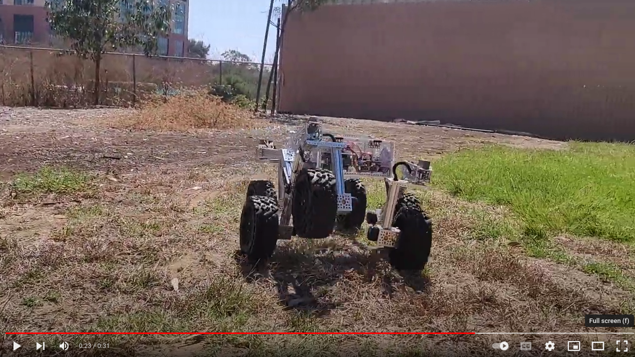
Photo credit
images/youtube-thumbnail.png
JPL / California Institute of Technology and Open Source Rover contributors · Apache-2.0Unmodified source image.
A gallery of some community builds including previous versions of the rover can be found here.
About the OSR
Motivation
JPL is always looking to inspire the next generation of scientists, engineers, and roboticists to help us explore and learn about our solar system (and beyond!). We release the plans for this rover as a way to try and give budding enthusiasts a fun robotics project that will help teach them and get them involved in robotics sooner and at a lower cost.
At a glance
Photo credit
images/osr-onshape.gif
JPL / California Institute of Technology and Open Source Rover contributors · Apache-2.0All animation frames retained; resized without cropping and converted to browser video.
The OSR has been around since 2017 and has undergone many iterations. It is a premium and robust robot with a unique look, high customizability, and powerful abilities. The hardware and electronics were designed with expansions like a head display and robot arm in mind.
| spec | value |
|---|---|
| top speed | ~1.6m/s (~slow running, subject to motor selection |
| nb motors | 10 |
| structural material | aluminum |
| total cost | ~$1600 (about the cost of a TurtleBot 3 Waffle) |
Photo credit
images/rover.png
JPL / California Institute of Technology and Open Source Rover contributors · Apache-2.0Unmodified source image.
The OSR mostly uses parts from GoBilda for the mechanical assembly. For GoBilda's (international) shipping options, see here.
Other open-source, cheaper alternatives exist but are slower, less strong, and are more fragile. See Additional Projects.
Features
This rover is designed to function similarly to the 6 wheel rover designs on Mars and employs a few of the major driving mechanics that the mars rovers use to traverse rocky surfaces:
- Rocker-Bogie: The Rocker-Bogie suspension system allows all 6 wheels to continually be in contact with the ground while climbing over obstacles
- Differential Pivot: Allows weight to be mechanically offloaded from one side of the rover to the other while climbing
- 6-Wheel Ackerman Steering: Driving and steering/turning mechanism that governs where the wheels point and how fast each of them will move.
A Raspberry Pi acts as the "brain" of this rover for its versatility, accessibility, simplicity, and ability to add and upgrade your own modifications. Any method with which you can communicate with a Raspberry Pi (bluetooth, WiFi, USB devices, etc) can be interfaced into the control system of the robot.
For a 7.2Ah battery and with some driving on rough terrain, expect to get at least 3 hours of drive time. Below chart was recorded while driving on rocky terrain and plots voltage, current draw, and commanded velocity over time. When the voltage drops below 13-14V, the rover will power down. You can increase drive time by getting a bigger battery and/or by having the rover carry a second battery that can be swapped out.
WARNING: Be careful to not discharge a LiPo battery too far as that drastically lowers the lifetime of your battery and can potentially make it hard or impossible to recharge.
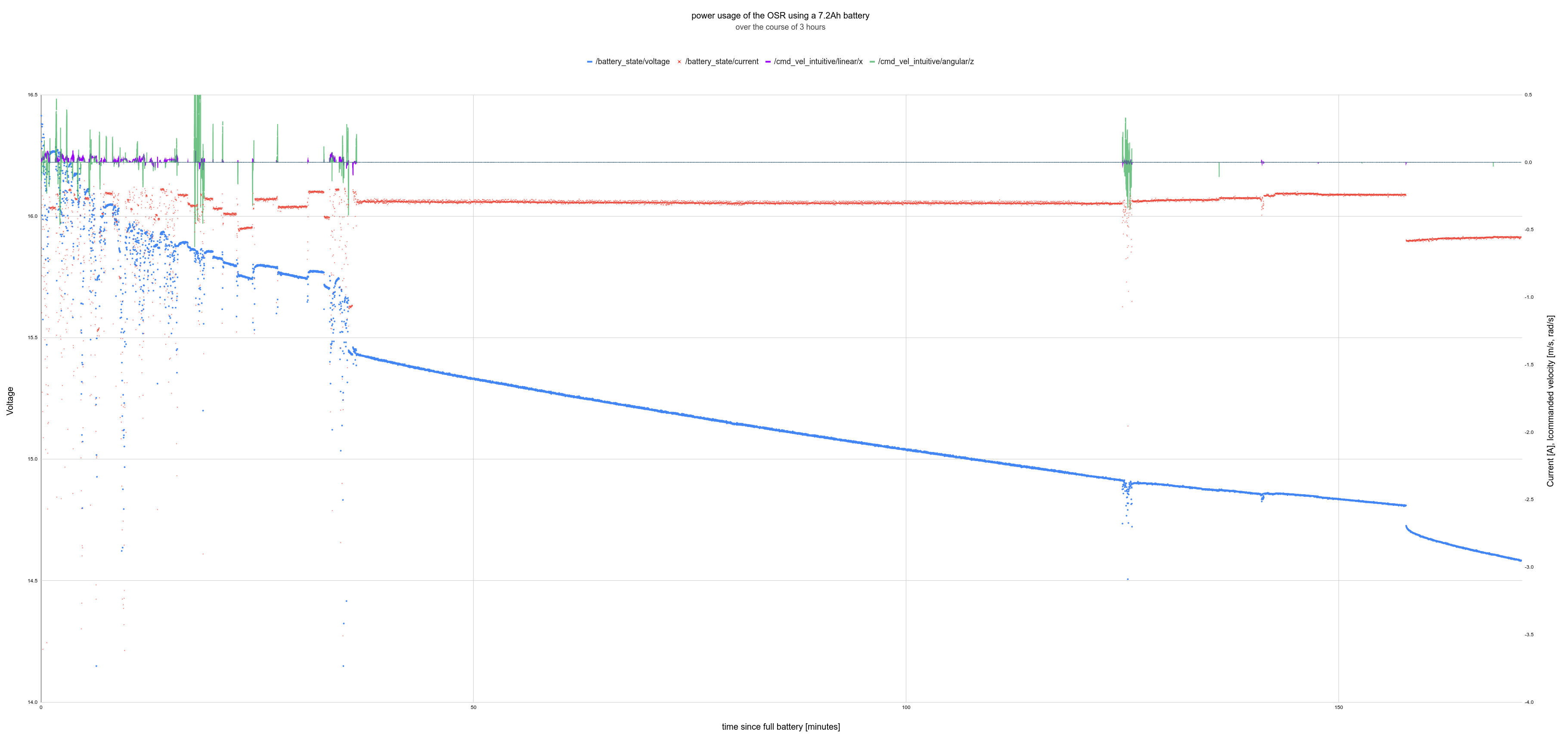
Photo credit
images/power_usage_osr.png
JPL / California Institute of Technology and Open Source Rover contributors · Apache-2.0Unmodified source image.
Join a community of hundreds of builders
Considering building one yourself? The best way to ask questions, reach maintainers, learn about modifications, and join the community of Open Source Rover builders is to join our Slack group:
Watch the original project video
Note: JPL and Caltech have no official affiliation with this forum; it is run by individuals of the general public. On these you can ask questions if you need help or clarification on any aspects of the project. Additionally, you can post and promote any modifications or addons that you have created on this project. We highly encourage additions and modifications to be posted so that this project and community can grow.
Maintenance Status
As an open-source hardware project, the rover is continuously improving. Please check issues, pull requests, and the Slack forum to see if any big changes are expected soon. The OSR project is proud to be Open-Source Hardware certified!
Online 3D Model
You can view a 3D model of the latest version of the rover in your browser at OnShape.
Skills Necessary
This project has elements in mechanical assembly/fabrication, uses a host of electrical components, and has software that will run it all. In order to complete this project, you will need to have some experience in the following:
- Fabrication/Machining: All parts are Consumer Off-The-Shelf (COTS) parts and no metal machining should be required to complete the 'base' version of the rover. However for any optional expansions, it may be useful to have access to the following skills/tools:
- Metal cutting using band saw/dremel
- Drilling using drill press/hand drill
- Filing and sanding for part cleanup
- General Fabrication/Machining Safety
- Electronics: This project uses components like motors, motor controllers, and batteries. While prior experience with the following skills is not required, having access to someone who can help will save a lot of time:
- Soldering
- Electrical debugging
- Wiring
- Electrical Safety
- Software: The rover's brain is a Raspberry Pi. All code can be found in the osr-rover-code repository along with step-by-step instructions to set it up. Basic familiarity with Linux, ROS, Git, and Python will be helpful though.
Most of the above are skills that you can learn and pick up fairly quickly from watching videos and doing research on the internet, and throughout the project we try to give supplemental information on some of these as well. See the build documents for more information.
Tools Necessary
This project assumes you have some standard tools to help assemble the project. If you do not have any of the optional tools, we provide examples of online services that you can use to have the parts fabricated and sent to you.
Mandatory tools
- Metric hex keys
- Pliers
- Wire Snips
- Wire Strippers
- Solder Iron
- Solder
- Digital Multimeter
- Wire strippers, e.g. these
Optional Tools
- 3D printer
- Laser Cutter (for the body plates, online services available)
- Benchtop Power Supply (to test without using battery)
- Items for operating a Raspberry Pi (Keyboard, mouse, monitor, 5V micro USB power adapter)
Expected time commitment
In our experience, this project takes no less than 100 person-hours to build, and depending on the familiarity and skill level of those involved could be significantly more. Experienced builders may be able to build this project in this amount of time. However, this project is generally meant to be a teaching and learning tool. Throughout the documentation, we try to give supplemental information for those who might be new to this kind of project.
Getting Started
Rover Build Roadmap
-
Stage 1: Order parts. You'll want to get started on this ASAP!
-
Stage 2: Create the wiring. The cables connect the Printed Circuit Board (PCB) in the body to each motor and integrate into the rocker-bogie and corner assemblies so they need to be built first.
-
Stage 3: Make the electronics: Soldering the PCB and installing into the rover along with peripheral connections. We'll also use the wiring to test your PCBs.
-
Stage 4: Make the mechanical assemblies: the body, the two rocker-bogies, the drive and corner motor assemblies. The instructions will guide you through how to do these step by step while integrating the cabling from Stage 2. You'll then attach them into something that will start to look like a rover!
-
Stage 5: Setting up and configuring the operating system rover code. The Rover Code repo's README files will walk you through all necessary steps for getting the rover software up and running on the Raspberry Pi. These steps can be completed at any point during the project, all the way up to when all the electronics and mechanical parts are completed and you are ready to start driving and controlling the robot.
-
What's next? Add your own upgrades! We chose Raspberry Pi as the brain of the project so that it should be easy to add, change, and upgrade to build exciting things on top of this already cool robot. Some upgrade ideas to get you brainstorming: sonar for collision detection, IMU for orientation / closed-loop driving / obstacle mapping, camera for object identification and tracking, sensor packages (temperature, pressure, humidity), solar panels, or even a robotic arm!
Ordering parts
Parts Lists
The Parts List Readme contains all the parts necessary to build the entirety of the robot as it is listed in our documentation.
Note that educational builders may apply for a 15% discount at GoBilda by filling out this form. Make sure you do this on time as processing times may vary.
You can select higher RPM motors (to drive your rover faster) at the sacrifice of max stall torque. A selection of motors that would integrate easily with the rest of the suggested rover design can be found at GoBilda - 5203 series. The rover design and the software can accommodate different wheel sizes if you find wheels you like better.
Additional Projects
Take a look at these alternative Mars rover replicas:
Star History
Disclaimer
Reference herein to any specific commercial product, process, or service by trade name, trademark, manufacturer, or otherwise, does not constitute or imply its endorsement by the United States Government or the Jet Propulsion Laboratory, California Institute of Technology. Government sponsorship acknowledged.
Licensed under Apache License 2.0.
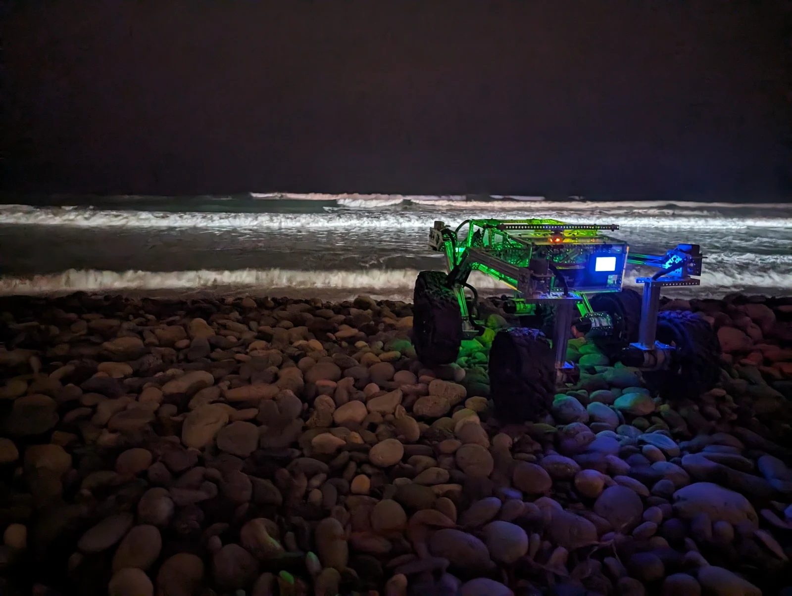
Photo credit
images/beach_osr.jpg
JPL / California Institute of Technology and Open Source Rover contributors · Apache-2.0Resized without cropping and converted to WebP.
Parts list
This file was autogenerated from the mechanical parts list and digikey BOM and should consist of the same parts, just presented in a more readable format. The Digikey csv file can be uploaded to Digikey.com directly to create a shopping cart. Before you place an order, please double check that you have all parts in the right quantities.
The total cost comes out to be $1421.18 without the GoBilda educational discount (15%) and excluding shipping. note: GoBilda may change its pricing without notice.
Parts for drive wheel assembly
| short name | link | cost per part | total # req | total cost |
|---|---|---|---|---|
| wheel | Wasteland Wheel (144mm Diameter, 52mm Width) | $24.99 | 6 | $149.94 |
| clamping mount | 1401 Series 2-Side, 2-Post Clamping Mount (43mm Width, 36mm Bore) - goBILDA | $6.99 | 6 | $41.94 |
| motor | 5203 Series Yellow Jacket Planetary Gear Motor (26.9:1 Ratio, 24mm Length 8mm REX™ Shaft, 223 RPM, 3.3 - 5V Encoder) | $42.99 | 6 | $257.94 |
| REX bore hub | 1310 Series Hyper Hub (8mm REX™ Bore) | $7.99 | 6 | $47.94 |
| 2 Hole U channel | 1120 Series U-Channel (2 Hole, 72mm Length) - goBILDA | $4.99 | 6 | $29.94 |
Cost to build these assemblies: $87.95 * 6 assemblies = $527.7
Parts for corner assembly
| short name | link | cost per part | total # req | total cost |
|---|---|---|---|---|
| 144mm goRail | 1109 Series goRAIL (144mm Length) - goBILDA | $5.49 | 4 | $21.96 |
| 4 Hole U channel | 1121 Series Low-Side U-Channel (4 Hole, 120mm Length) - goBILDA | $5.99 | 4 | $23.96 |
Cost to build these assemblies: $11.48 * 4 assemblies = $45.92
Parts for rocker bogie assembly
Cost to build these assemblies: $211.91 * 2 assemblies = $423.83
Parts for body assembly
Cost to build this assembly: $253.67
Parts for general assembly
| short name | link | cost per part | total # req | total cost |
|---|---|---|---|---|
| hurricane nuts | Hurricane Nut for goRAIL - 25 Pack - goBILDA | $9.99 | 1 | $9.99 |
| wire grommets | Plastic Grommet (14-1) - 12 Pack - goBILDA | $1.99 | 1 | $1.99 |
| M4 washers | Zinc Plates Steel Washer (M4 x 8mm OD) - 25 Pack - goBILDA | $1.99 | 1 | $1.99 |
| M4 nuts | Zinc Plates Steel Hex Nut (M4 x 7) - 25 Pack - goBILDA | $2.49 | 4 | $9.96 |
| M4 locknuts | Zinc Plates Steel Locknut (M4 x 7) - 25 Pack - goBILDA | $2.99 | 1 | $2.99 |
| M4x6 button screws | M4x6 Button Screw 25-pack | $2.99 | 2 | $5.98 |
| M4x10 button screws | M4x10 Button Screw 25-pack | $3.39 | 3 | $10.17 |
| M4x16 button screws | M4x16 Button Screw 25-pack | $3.79 | 2 | $7.58 |
| M4x8 socket screws | M4x8 Socket Screw 25-pack | $3.19 | 2 | $6.38 |
| M4x10 socket screws | M4x10 Socket Screw 25-pack | $3.19 | 3 | $9.57 |
| M4x12 socket screws | M4x12 Socket Screw 25-pack | $3.19 | 1 | $3.19 |
| M4x16 socket screws | M4x16 Socket Screw 25-pack | $3.19 | 2 | $6.38 |
| M4x20 socket screws | M4x20 Socket Screw 25-pack | $3.09 | 1 | $3.09 |
Cost to build this assembly: $79.26
Parts for electrical assembly
| short name | link | cost per part | total # req | total cost |
|---|---|---|---|---|
| A1: CAP CER 10000PF 50V X7R RADIAL | 399-9865-1-ND | $0.164 | 20 | $3.28 |
| A2: CAP ALUM 100UF 20% 50V RADIAL | 399-18272-1-ND | $0.248 | 10 | $2.48 |
| A3: CAP CER 0.1UF 50V X7R RADIAL | 399-14065-1-ND | $0.211 | 10 | $2.11 |
| A4: CAP ALUM 10UF 20% 50V RADIAL | 399-ESK106M050AC3DACT-ND | $0.162 | 10 | $1.62 |
| A5: DIODE SCHOTTKY 25V 10A TO220AC | 497-2738-5-ND | $1.93 | 2 | $3.86 |
| A6: DIODE GEN PURP 75V 300MA DO35 | 1655-1N4148CT-ND | $0.108 | 10 | $1.08 |
| A7: FUSEHOLDER BLOCKS - PCB - CLIP C | 732-11376-ND | $0.68 | 1 | $0.68 |
| A10: CONN HEADER VERT 12POS 2.54MM | TSW-104-07-F-T-ND | $1.5 | 4 | $6.0 |
| A11: CONN HEADER VERT 8POS 2.54MM | S1012E-08-ND | $0.47 | 4 | $1.88 |
| A12: CONN HDR 20POS 0.1 TIN PCB | S7078-ND | $1.3 | 1 | $1.3 |
| A13: CONN HEADER VERT 40POS 2.54MM | S9175-ND | $0.73 | 2 | $1.46 |
| A14: CONN HEADER VERT 6POS 2MM | 455-1708-ND | $0.36 | 2 | $0.72 |
| A16: CONN HEADER VERT 20POS 2.54MM | WM6548-ND | $2.52 | 1 | $2.52 |
| A17: CONN HDR 2POS 0.1 TIN PCB | S7000-ND | $0.32 | 5 | $1.6 |
| A19: TERM BLK 2P SIDE ENT 5.08MM PCB | ED2580-ND | $0.73 | 2 | $1.46 |
| A20: CONN HEADER VERT 6POS 4.2MM | 1726750613-ND | $2.27 | 6 | $13.62 |
| A21: TRANS PNP 40V 0.2A TO92-3 | 2N3906TAFSCT-ND | $0.285 | 10 | $2.85 |
| A22: RES 100 OHM 5% 1/4W AXIAL | CF14JT100RCT-ND | $0.056 | 10 | $0.56 |
| A23: RES 10K OHM 5% 1/4W AXIAL | CF14JT10K0CT-ND | $0.056 | 10 | $0.56 |
| A24: RES 4.7K OHM 5% 1/4W AXIAL | CF14JT4K70CT-ND | $0.0404 | 25 | $1.01 |
| A25: RES 0 OHM JUMPER 1/4W AXIAL | CD14ZT0R00CT-ND | $0.079 | 10 | $0.79 |
| A26: RES 68 OHM 5% 1/8W AXIAL | CF18JT68R0CT-ND | $0.045 | 10 | $0.45 |
| A27: RES 82 OHM 5% 1/4W AXIAL | CF14JT82R0CT-ND | $0.056 | 10 | $0.56 |
| A28: RES 1K OHM 5% 1/4W AXIAL | CF14JT1K00CT-ND | $0.056 | 10 | $0.56 |
| A29: RES 680 OHM 5% 1/4W AXIAL | CF14JT680RCT-ND | $0.056 | 10 | $0.56 |
| A30: RES 220 OHM 5% 1/4W AXIAL | CF14JT220RCT-ND | $0.056 | 10 | $0.56 |
| A32: SWITCH SLIDE DIP SPDT 50MA 24V | CT206124-ND | $1.25 | 1 | $1.25 |
| A37: LED BAR GRAPH 10SEG 570NM GRN | 754-2186-ND | $3.26 | 2 | $6.52 |
| A38: IC REG LINEAR 3.3V 750MA TO220-3 | 576-2235-ND | $3.02 | 2 | $6.04 |
| B1: FUSE GLASS 10A 125VAC 5X20MM | F3631-ND | $1.21 | 2 | $2.42 |
| B9: SWITCH TOGGLE ON-OFF-ON | 708-3060-ND | $3.28 | 1 | $3.28 |
| B11: TERM BLOCK HDR 24POS VERT 5MM | ED1682-24-ND | $3.33 | 1 | $3.33 |
| A9: TERM BLOCK HDR 6POS VERT 3.5MM | WM25701-ND | $2.02 | 3 | $6.06 |
| B2: TERM BLOCK PLUG 6POS STR 3.5MM | WM13033-ND | $2.59 | 3 | $7.77 |
Cost to build this assembly: $90.8
Extra Parts
These parts you may either already have, depend on where you're located for a good deal, depend on personal preference, or are optional. If you do not have any of these, you'll need to add around $500 to the total project cost.
Note: Make sure to go through the list below to make sure you have everything you need.
The PCBs
The electronics of the rover consist of two boards: the brain board and the motor board. To order these boards we suggest that you order from JLCPCB, this PCB fabrication company is quite inexpensive for this board size and has good turnaround time. You'll either have to order the required minimum of 10 pieces or you can ask on the Slack group whether someone wants to put in a group order or already has some extras. Upload the .zip files individually — one for the brain board and one for the motor board — and make sure the following settings are set:
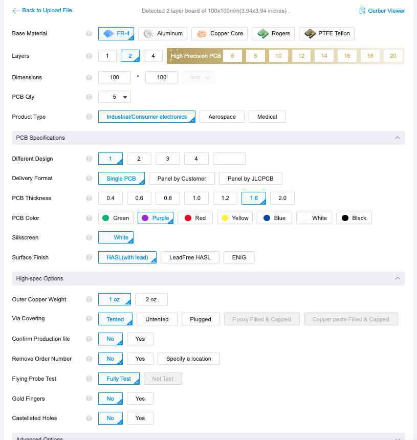
Photo credit
electrical/pcb/control_board/gerbers/jlcpcb_ordering.png
JPL / California Institute of Technology and Open Source Rover contributors · Apache-2.0Unmodified source image.
The body plates
The body plates that attach to all sides of the body are designed to be made from laser cut acrylic, MDF, hardwood, or similar. The 2D cutout files are the .dxf files in the laser cut parts folder. They were designed to be around 3mm thick (1/8"). You can choose a material and cut them at your local makerspace's laser cutter or order them from an online service like Sculpteo or SendCutSend. Check the README in that folder for more details.
A gamepad or remote controller
This is technically not a requirement, especially if you're planning on making the rover autonomous, but is highly recommended. Any USB based option should work here.
Some options are getting an XBox controller with a usb dongle or for longer range; the pricier Spektrum WS2000 with Spektrum DXs transmitter. Many alternatives exist and will work ok.
Standoff kit for the boards
You'll want these to mount the PCBs to the rover body. Many options exist here, for example this kit.
Wiring
We recommend getting spools of 18AWG (red and black), 20AWG (white, red, black) and 22AWG wire (4 colors). The wire has to be stranded and not solid core as it will bend during operation. For each wire type, if possible, get ribbon cable where each wire is attached to another one which will help with keeping wiring clean and manageable.
To protect the cables from chafing against the sharp aluminum parts, we recommend cable sleeves. You can also use grommets, filing down the sharp edges or burs, applying tape to the edges, or using expandable wire sleeving.
Heat shrink is a must have for keeping cables nice and snug.
Take a look at the wiring overview to get an idea of what you will be building. You'll need crimps and connectors for DuPont, Bullet, XT30, JST, and Molex styles. Crimping doesn't have a 100% success rate, so we recommend getting extras or buying a kit if you're planning on using them for other projects as well. Here are some options for each set you need:
- A Raspberry Pi ribbon cable, e.g. from Adafruit but available in many places. While you could use header pins for this connection, the cable is the cleanest solution
- A USB-C power breakout cable if you're using a Raspberry Pi 5, e.g. from Amazon
- XT30 connectors for the power connections on the motor PCB.
- DIY options, either:
- premade from GoBilda: 2x male leads, 2x female leads
- 6 4-pin JST connections:
- 6 6-pin Molex PCI-E connections. Digikey carries a couple options. In either case, be sure to get enough for 6 connectors.
- housings and pins
- assemblies are sometimes available but the 16 AWG wire may be difficult to work with
- 4 3-pin DuPont and 8 4-pin DuPont connectors
- DuPont connector kit
- Buy precrimped wires+connectors from various sources
- 12 female 3.5mm Bullet connectors. Make sure you're getting the right size connectors and ones that come insulated.
- GoBilda has various combinations available that you can cut/solder/crimp. They use 16AWG wire which is on the thicker side. Make sure you're getting the Female connector type.
- Buy a DIY kit
- The GoBilda connector pack is good quality but only has 5 female connectors so you would need 3 of them.
- from Amazon (insulators are flimsy but ok)
Threadlocker
You will want threadlocker for several screws so that they don't unscrew themselves while driving. You can find this everywhere, for example at Gobilda. Make sure you get blue as opposed to red so it's not permanent.
Tools
- A combination nut driver will save you time screwing and unscrewing (lock)nuts inside the body.
- You'll need 2.5mm and 3mm hex keys for the button and socket M4 screws respectively. For example Gobilda 2.5 and Gobilda 3.
- A crimping tool for Molex, JST, DuPont connectors. A regular crimping tool should be able to handle all of these without issue. While you can technically complete a crimp without a crimping tool, it often won't be as consistent or strong as with a proper crimper. Various connector sets come with a decent crimper.
Electrical
- Voltage Regulators:
- 3 X Roboclaw 2x7A Motor Controller Basic Micro
- 1 X Power Measurement Unit INA260: Sold out on DigiKey, possible replacements are on Adafruit
- 1 X PCA9685 steering servo driver Mouser
- DC power meter: Amazon. This LCD display reads out current, voltage, power, and energy, and can be put on the back where the rectangular hole is in the laser cut cover.
- batteries: many options available here. We recommend getting LiPo batteries. You'll need a battery that can provide over 14V(*), so a 4s battery works well. You can get batteries with various mAh ratings (how many milliAmperes the battery can output for 1 hour). We recommend any option over 4000mAh. Higher capacity comes at a higher cost. You can also get more than one battery and swap them out. The rover can carry them as well.
- Zeee sells many options on Amazon
- You'll also need a charger for the battery. Make sure it can support the battery you bought, chemistry-wise and connector-wise. For the Zeee options, this B6 Lipo Balance Charger from Amazon will work.
- Consider getting a fireproof battery bag. LiPo batteries are extremely flammable/explosive and a fire caused by a battery is extremely difficult to put out.
- You'll also need a way to connect your battery to the PCB via a XT30 connector (MH-FC) which depends on the battery you get. Often these come with the charger for the battery
- A Raspberry Pi 3, 4, or 5 and SD card for the operating system. For the 4 or 5, any amount of RAM should work just fine. Note that only the 5 has two full serial interfaces and thus is the only model that can connect to the motor controllers (Roboclaws) and run bluetooth at the same time.
(*) The reason you need 14V is that the 12V regulator needs a dropout voltage on top of the output voltage in order to provide 12V. A 12V battery will not work adequately.
Different wheels
- The wheels we previously included as the default from DollarHobbyz are $34.95 per pair of two for a total of $104.85 (excl. shipping), saving ~$135 compared to the default Wasteland wheels. They are a perfectly fine choice but require some drilling to fit to the motor hubs.
- Gobilda also sells a larger version of the Wasteland Wheel at 192mm diameter. This adds $90 total compared to the default Wasteland wheels. No drilling is required. Those wheels are bigger and wider and look like this:
| smaller Wasteland wheels | bigger Wasteland wheels |
|---|---|
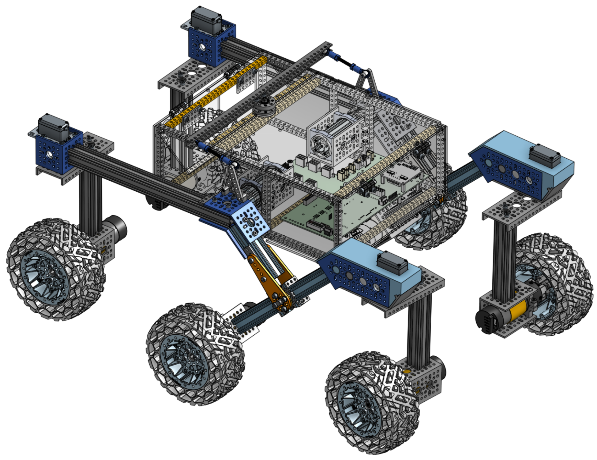 Photo creditparts_list/smaller_wasteland.png JPL / California Institute of Technology and Open Source Rover contributors · Apache-2.0Unmodified source image. | 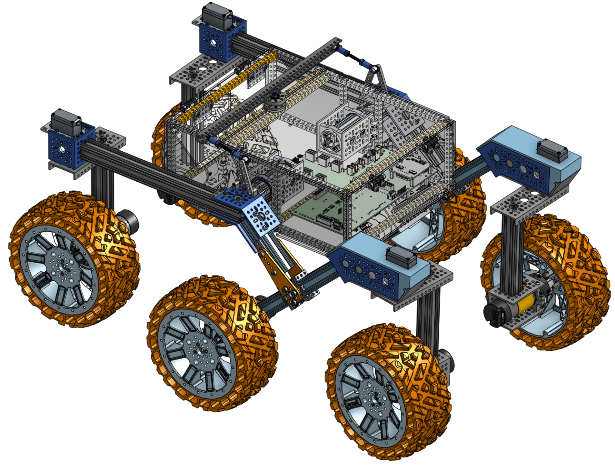 Photo creditparts_list/bigger_wasteland.png JPL / California Institute of Technology and Open Source Rover contributors · Apache-2.0Unmodified source image. |
There is a software parameter where you can easily modify the size of the wheels to account for speed differences.
Maintaining the Parts List
Parts can become out of stock or discontinued in the future. In this case, the part list can be modified by editing parts_list.csv, which covers all the mechanical parts, digikey_bom.csv, which covers most of the electrical part, and extra_parts.md to cover the rest. After doing so, you can compile to update the README.md file using csv_to_md.py (The compilation will also happen automatically with a merge). Do not edit README.md directly, as it will be overwritten by the compilation process.
Screws tally
All of the below are included in the parts list. This document is for maintenance only.
M4
| subassembly | nb | length | type | purpose | multiplier | total |
|---|---|---|---|---|---|---|
| wheel | 3 | 16 or 18 | socket | wheel - motor | 6 | 18 |
| wheel | 4 | 10 | either | motor - channel | 6 | 24 |
| wheel | 3 | 10 | button | bracket - vert. extrusion | 6 | 18 |
| wheel | 3 | 10 or 12 | socket | wheel - motor axis clamp | 6 | 18 |
| corner | 3 | 10 | button | vert. extrusion - low channel | 4 | 12 |
| corner | 3 | 10 | button | low channel - servo shaft | 4 | 12 |
| corner | 3 | 10 | either | servo bracket - rocker | 4 | 12 |
| corner | 3 | 10 | either | servo bracket - rocker | 4 | 12 |
| corner | 6 | 6 or 8 or 10 | button | servo - channel | 4 | 24 |
| rocker-bogie | 8 | 12 | socket | rocker-bogie joint | 2 | 16 |
| rocker-bogie | 8 | 10 or 12 | socket | rocker-bogie joint - extrusion | 2 | 16 |
| rocker-bogie | 13 | 8 | socket | rocker-bogie - body-axis | 2 | 26 |
| rocker-bogie | 2 | 6 or 8 | socket | rocker-bogie - diff pivot | 2 | 4 |
| rocker-bogie | 8 | 8 | socket | rocker-bogie joint | 2 | 16 |
| rocker-bogie | 6 | 10 | socket | rocker-bogie joint | 2 | 12 |
| rocker-bogie | 4 | 10 or 12 | socket | diff pivot - rocker-bogie | 1 | 4 |
| rocker-bogie | 4 | 20 or 22 | socket | turnbuckles | 1 | 4 |
| rocker-bogie | 2 | 6 | button | diff pivot shaft - bearing | 1 | 2 |
| body | 28 | 16 | socket | structure | 1 | 28 |
| body | 34 | 16 | button | body plates | 1 | 34 |
| body axis | 4 | 18 or 20 | socket | axis - body | 2 | 8 |
| body axis | 8 | 6 or 8 | button | bearing - channel | 2 | 16 |
| body axis | 2 | 6 | either | axis cap | 2 | 4 |
| hinges | 2 | 6 or 8 | button | 4 | 8 | |
| hinges | 2 | 6 or 8 | either | 4 | 8 | |
| hinges | 2 | 14 or 16 | either | 4 | 8 | |
| hinges | 1 | 10 | button | 4 | 4 |
When multiple options are available, the bold value is selected.
Total per category and length:
| type | length | min required | Gobilda # of 25-packs |
|---|---|---|---|
| button | 6 | 10 (+4) | 2 |
| button | 10 | 70 (+48) | 3 |
| button | 16 | 34 | 2 |
| socket | 8 | 30 (+8) | 2 |
| socket | 10 | 46 (+52) | 4 |
| socket | 12 | 20 | 1 |
| socket | 16 | 46 (+8) | 2 |
| socket | 20 | 12 | 1 |
Values between parentheses are the additional screws that would need to be ordered if all 'either' types with same length are used in that type. In general, socket screws are preferred because of their resistance to stripping and use of a larger hex key.
The parts list also includes 1 25-pack of M4 washers, 2 25-pack of M4 hex nuts, and 1 25-pack of M4 locking hex nuts.
Extra Parts
These parts you may either already have, depend on where you're located for a good deal, depend on personal preference, or are optional. If you do not have any of these, you'll need to add around $500 to the total project cost.
Note: Make sure to go through the list below to make sure you have everything you need.
The PCBs
The electronics of the rover consist of two boards: the brain board and the motor board. To order these boards we suggest that you order from JLCPCB, this PCB fabrication company is quite inexpensive for this board size and has good turnaround time. You'll either have to order the required minimum of 10 pieces or you can ask on the Slack group whether someone wants to put in a group order or already has some extras. Upload the .zip files individually — one for the brain board and one for the motor board — and make sure the following settings are set:
Photo credit
electrical/pcb/control_board/gerbers/jlcpcb_ordering.png
JPL / California Institute of Technology and Open Source Rover contributors · Apache-2.0Unmodified source image.
The body plates
The body plates that attach to all sides of the body are designed to be made from laser cut acrylic, MDF, hardwood, or similar. The 2D cutout files are the .dxf files in the laser cut parts folder. They were designed to be around 3mm thick (1/8"). You can choose a material and cut them at your local makerspace's laser cutter or order them from an online service like Sculpteo or SendCutSend. Check the README in that folder for more details.
A gamepad or remote controller
This is technically not a requirement, especially if you're planning on making the rover autonomous, but is highly recommended. Any USB based option should work here.
Some options are getting an XBox controller with a usb dongle or for longer range; the pricier Spektrum WS2000 with Spektrum DXs transmitter. Many alternatives exist and will work ok.
Standoff kit for the boards
You'll want these to mount the PCBs to the rover body. Many options exist here, for example this kit.
Wiring
We recommend getting spools of 18AWG (red and black), 20AWG (white, red, black) and 22AWG wire (4 colors). The wire has to be stranded and not solid core as it will bend during operation. For each wire type, if possible, get ribbon cable where each wire is attached to another one which will help with keeping wiring clean and manageable.
To protect the cables from chafing against the sharp aluminum parts, we recommend cable sleeves. You can also use grommets, filing down the sharp edges or burs, applying tape to the edges, or using expandable wire sleeving.
Heat shrink is a must have for keeping cables nice and snug.
Take a look at the wiring overview to get an idea of what you will be building. You'll need crimps and connectors for DuPont, Bullet, XT30, JST, and Molex styles. Crimping doesn't have a 100% success rate, so we recommend getting extras or buying a kit if you're planning on using them for other projects as well. Here are some options for each set you need:
- A Raspberry Pi ribbon cable, e.g. from Adafruit but available in many places. While you could use header pins for this connection, the cable is the cleanest solution
- A USB-C power breakout cable if you're using a Raspberry Pi 5, e.g. from Amazon
- XT30 connectors for the power connections on the motor PCB.
- DIY options, either:
- premade from GoBilda: 2x male leads, 2x female leads
- 6 4-pin JST connections:
- 6 6-pin Molex PCI-E connections. Digikey carries a couple options. In either case, be sure to get enough for 6 connectors.
- housings and pins
- assemblies are sometimes available but the 16 AWG wire may be difficult to work with
- 4 3-pin DuPont and 8 4-pin DuPont connectors
- DuPont connector kit
- Buy precrimped wires+connectors from various sources
- 12 female 3.5mm Bullet connectors. Make sure you're getting the right size connectors and ones that come insulated.
- GoBilda has various combinations available that you can cut/solder/crimp. They use 16AWG wire which is on the thicker side. Make sure you're getting the Female connector type.
- Buy a DIY kit
- The GoBilda connector pack is good quality but only has 5 female connectors so you would need 3 of them.
- from Amazon (insulators are flimsy but ok)
Threadlocker
You will want threadlocker for several screws so that they don't unscrew themselves while driving. You can find this everywhere, for example at Gobilda. Make sure you get blue as opposed to red so it's not permanent.
Tools
- A combination nut driver will save you time screwing and unscrewing (lock)nuts inside the body.
- You'll need 2.5mm and 3mm hex keys for the button and socket M4 screws respectively. For example Gobilda 2.5 and Gobilda 3.
- A crimping tool for Molex, JST, DuPont connectors. A regular crimping tool should be able to handle all of these without issue. While you can technically complete a crimp without a crimping tool, it often won't be as consistent or strong as with a proper crimper. Various connector sets come with a decent crimper.
Electrical
- Voltage Regulators:
- 3 X Roboclaw 2x7A Motor Controller Basic Micro
- 1 X Power Measurement Unit INA260: Sold out on DigiKey, possible replacements are on Adafruit
- 1 X PCA9685 steering servo driver Mouser
- DC power meter: Amazon. This LCD display reads out current, voltage, power, and energy, and can be put on the back where the rectangular hole is in the laser cut cover.
- batteries: many options available here. We recommend getting LiPo batteries. You'll need a battery that can provide over 14V(*), so a 4s battery works well. You can get batteries with various mAh ratings (how many milliAmperes the battery can output for 1 hour). We recommend any option over 4000mAh. Higher capacity comes at a higher cost. You can also get more than one battery and swap them out. The rover can carry them as well.
- Zeee sells many options on Amazon
- You'll also need a charger for the battery. Make sure it can support the battery you bought, chemistry-wise and connector-wise. For the Zeee options, this B6 Lipo Balance Charger from Amazon will work.
- Consider getting a fireproof battery bag. LiPo batteries are extremely flammable/explosive and a fire caused by a battery is extremely difficult to put out.
- You'll also need a way to connect your battery to the PCB via a XT30 connector (MH-FC) which depends on the battery you get. Often these come with the charger for the battery
- A Raspberry Pi 3, 4, or 5 and SD card for the operating system. For the 4 or 5, any amount of RAM should work just fine. Note that only the 5 has two full serial interfaces and thus is the only model that can connect to the motor controllers (Roboclaws) and run bluetooth at the same time.
(*) The reason you need 14V is that the 12V regulator needs a dropout voltage on top of the output voltage in order to provide 12V. A 12V battery will not work adequately.
Different wheels
- The wheels we previously included as the default from DollarHobbyz are $34.95 per pair of two for a total of $104.85 (excl. shipping), saving ~$135 compared to the default Wasteland wheels. They are a perfectly fine choice but require some drilling to fit to the motor hubs.
- Gobilda also sells a larger version of the Wasteland Wheel at 192mm diameter. This adds $90 total compared to the default Wasteland wheels. No drilling is required. Those wheels are bigger and wider and look like this:
| smaller Wasteland wheels | bigger Wasteland wheels |
|---|---|
Photo creditparts_list/smaller_wasteland.png JPL / California Institute of Technology and Open Source Rover contributors · Apache-2.0Unmodified source image. | Photo creditparts_list/bigger_wasteland.png JPL / California Institute of Technology and Open Source Rover contributors · Apache-2.0Unmodified source image. |
There is a software parameter where you can easily modify the size of the wheels to account for speed differences.
Maintaining the Parts List
Parts can become out of stock or discontinued in the future. In this case, the part list can be modified by editing parts_list.csv, which covers all the mechanical parts, digikey_bom.csv, which covers most of the electrical part, and extra_parts.md to cover the rest. After doing so, you can compile to update the README.md file using csv_to_md.py (The compilation will also happen automatically with a merge). Do not edit README.md directly, as it will be overwritten by the compilation process.
Wiring
The wiring is what connects each of the 10 motors to the motor board carrying power and data. While creating the wiring requires a bit of patience, it's important that it's done properly so there's a consistent connection to the motors. Loose wires mean that the rover will not work as well or at all. Mechanical assemblies are more easily repaired than faulty wiring. If you have all parts ready to go, it could take between 2 and 5 hours to complete, depending on your skill level with crimping.
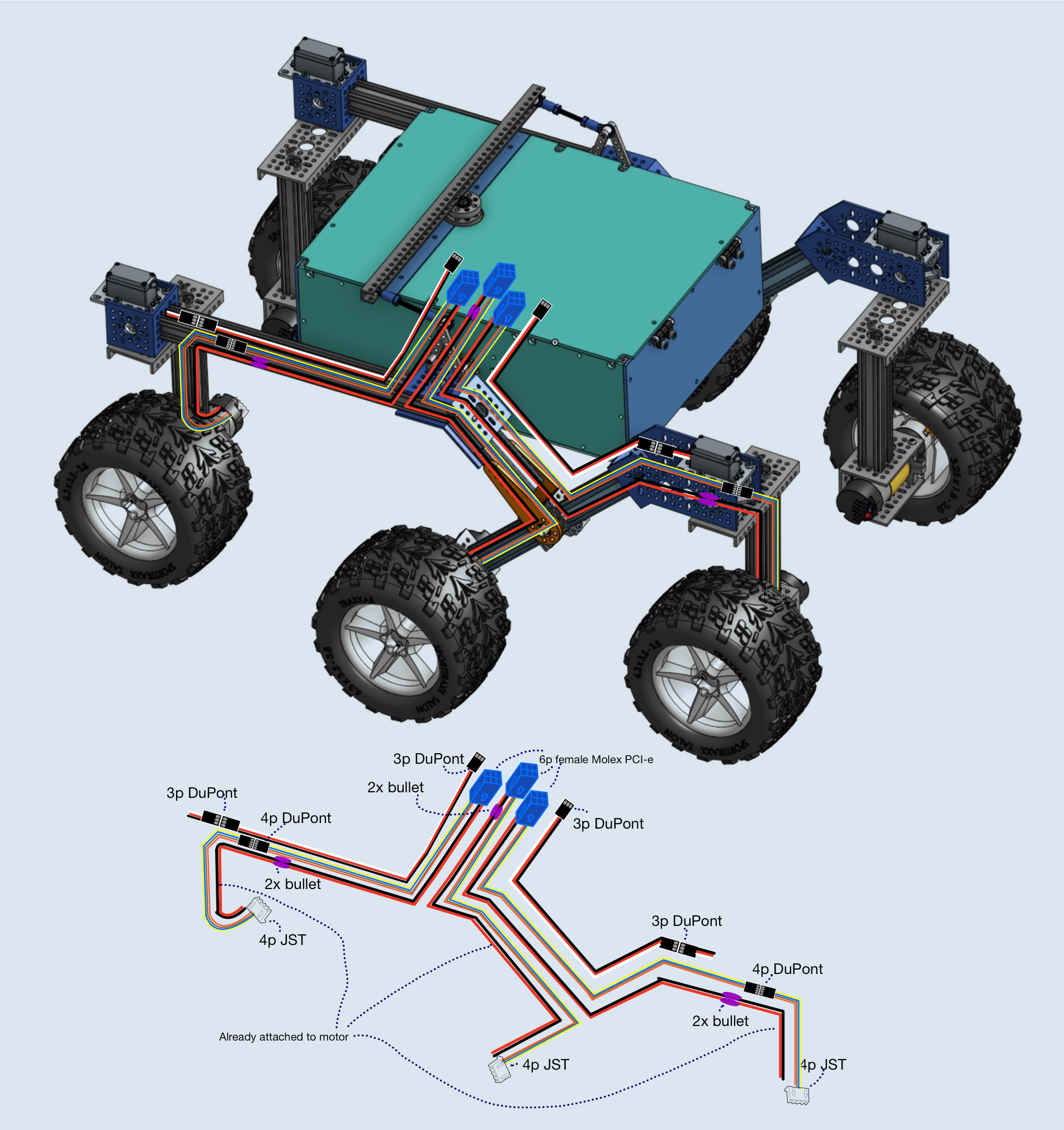
Photo credit
electrical/wiring/images/wiring_diagram.png
JPL / California Institute of Technology and Open Source Rover contributors · Apache-2.0Unmodified source image.
Harness diagrams further below were generated with WireViz and can be re-generated with the generateHarness.bat/.sh scripts.
Some notes on terminology:
Wiring harness (also called cable harness or wire assembly): the collective term for all the wiring and cables that are run through a system to connect power sources, sensors, data lines, etc. In the case of the rover, this means the cables that feed power to the motors, the control signals to the servos, and the encoder data back to the control boards.
Cable: A group of wires/conductors, usually with an outer sheath.
Wire: A single conductor, solid or stranded core, of any gauge.
Overview
We will be building several cables, all visualized in the above diagram. Make sure you have all wire types and connectors and understand the routing of the cabling as it will save you time down the line.
- 4x: JST female 4pin ↔ Dupont female 4pin (connects to (2))
- We'll use these to connect the drive motor encoders at the corners to the top of each corner
- Having an intermediate connection allows us to swap out motors, perform testing, and route the wires through the parts much easier.
- These are all of length 35cm (all lengths excluding connector length)
- You can also buy 4 premade cables from Gobilda. They are a bit shorter so you can make the wires in Step (2) 5cm longer without any issue.
- 4x: Dupont male 4pin ↔ 4-pins of female Molex connectors
- These will connect the drive motor encoders for each corner to the PCB through the rocker-bogie. The DuPont male side will plug into (1)
- The Molex connectors will be inserted in the 6-pin PCI-E connector
- 2 of these should be 52cm long for the front, the other 2 should be 45cm long for the back
- 2x: JST female 4pin ↔ 4-pins of female Molex connectors
- These will connect the drive motor encoders for the two middle wheels to the PCB
- The Molex connectors will be inserted in the 6-pin PCI-E connector that plugs into the PCB
- These will both be 53cm long
- 6x: 2-pin female bullet connector ↔ 2-pin female Molex connector
- These will connect the two drive motor power supplies (M+ and M-) to the PCB
- 2 of these are 2cm long for the middle wheels
- 2 of these are 53cm long for the front wheels
- 2 of these are 40cm long for the back wheels
- 4x: Dupont male 3pin ↔ DuPont female 3pin connectors
- These will connect the corner servo motors to the PCB
- 2 of these are 53cm long for the front corner servos
- 2 of these are 35cm long for the back corner servos
In total: 24 JST female crimps, 6 JST female connectors, 36 female DuPont crimps, 6 MH-FC PCI-E connectors, 28 male DuPont crimps, 16 female DuPont crimps, 4 3pin DuPont connectors, 8 4pin DuPont connectors, and 12x bullet connectors+crimps.
The harness diagrams in this README also contain an integrated bill-of-materials (BOM) for each cable so you can organize the parts appropriately.
Tip: Rather than crimp each wire yourself, you can buy premade connectors, cut the wires, and then solder them to the other side. For soldering using a heat gun, you could get something like the following: heat gun solder seal wire. This depends on your preferences. When using premade connectors, be extra careful of the pinouts so you connect the correct wire ends together.
Tip: For the thinner (AWG20 and AWG22) wiring we strongly recommend using ribbon cable (where each wire strand is attached to the next) to keep wires clean and strong. Alternatively you can twist the wires which also helps reduce interference from electrical noise.
Cut the wires to length
We want to be consistent with the color coding of your wires so we can troubleshoot easier. For example M+ (motor positive) should always be red and M- black for all drive motors. We'll also use the same colored wires for all encoders. We'll add one centimeter to each piece of wire for inserting into the connectors.
As can be seen on the diagram, we'll have three color coded types:
- servo wire: white, red, and black for the servo motors. The servo motors already have wires in these colors. wire gauge: 20AWG.
- Cut 2 pieces of 53+1=54cm
- 2 pieces of 36cm
- encoder wire: 4 colors of your choice for the drive motor encoders (in diagram: yellow, blue, brown, orange). wire gauge: 22AWG.
- Cut 4 pieces of length 35+1=36cm
- 2 pieces of 53cm
- 2 pieces of 46cm
- 2 pieces of 54cm
- power wire black and red for the drive motor power. wire gauge: 18AWG.
- Cut 2 pieces (of red and black wire) of 2+1=3cm
- 2 pieces of 54cm
- 2 pieces of 41cm
Optional but recommended: put two pieces of heat shrink on each set of wires. This allows you to securely remove a connection without accidentally stressing one wire/crimp too much. It also prevents the wires from detaching from one another.
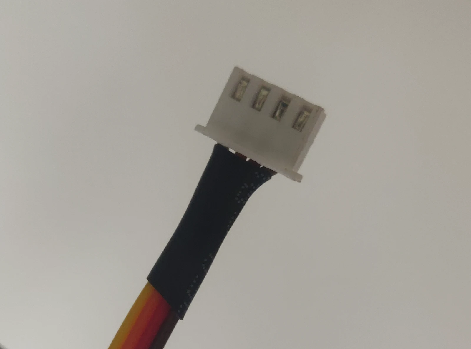
Photo credit
electrical/wiring/images/drive_motor_encoders.jpg
JPL / California Institute of Technology and Open Source Rover contributors · Apache-2.0Resized without cropping and converted to WebP.
Step (1) 4x: JST female 4pin ↔ Dupont female 4pin
Use the 4 pieces of 36cm encoder wire. Separate the wire ends from the ribbon cable so you can attach crimps to each wire. Using a wire stripper, remove about 3mm of wire protector from each wire. On one side of each 4-wire cable, use a crimping tool to attach a female JST crimp to each wire.
Tip: There are many great resources online to learn how to crimp effectively. Put the crimp into the crimping tool and lightly clamp down so the crimp doesn't fall out. Then inside the wire end and complete the crimp. When you have completed the crimp, give it a solid tug to test if it's properly attached. Loose crimps will backfire later!
On the other side of the cable, you will attach 4 Dupont female crimps. You now have one of 4 crimped wires, so repeat the process for the 3 other wires.
Now we'll insert each crimped cable into the appropriate connectors. Start by writing the pinout on each of the connectors for easy troubleshooting using a sharpie: B, A, G, 5 for channel B, channel A, ground, and +5V respectively. Copy over the annotations from the images below to your connectors, paying close attention to the orientation of each connector. Use the harness diagram below as a guide to make sure that each connector is in the right position in its housing.
Tip: On single row connectors like the JST-XH and the DuPont, there is usually a mark on the connector housing (like a triangle or a cutout) that indicates position 1. These are more visible in the harness diagrams.
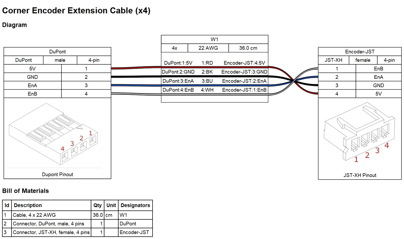
Photo credit
electrical/wiring/images/encoder_extension.jpg
JPL / California Institute of Technology and Open Source Rover contributors · Apache-2.0Resized without cropping and converted to WebP.
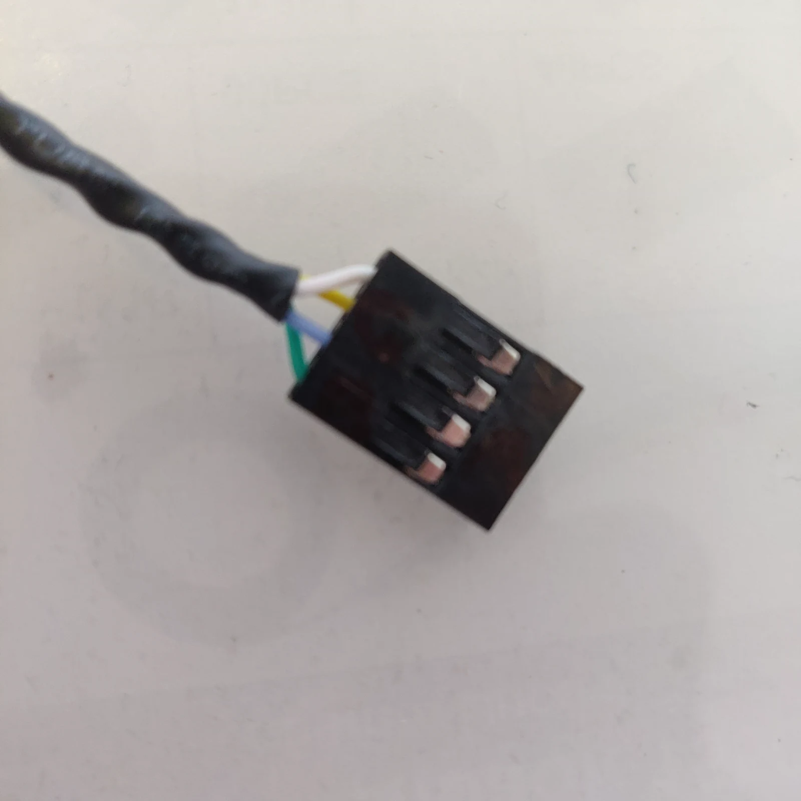 Photo creditelectrical/wiring/images/4p-DuPont.jpg JPL / California Institute of Technology and Open Source Rover contributors · Apache-2.0Resized without cropping and converted to WebP. | 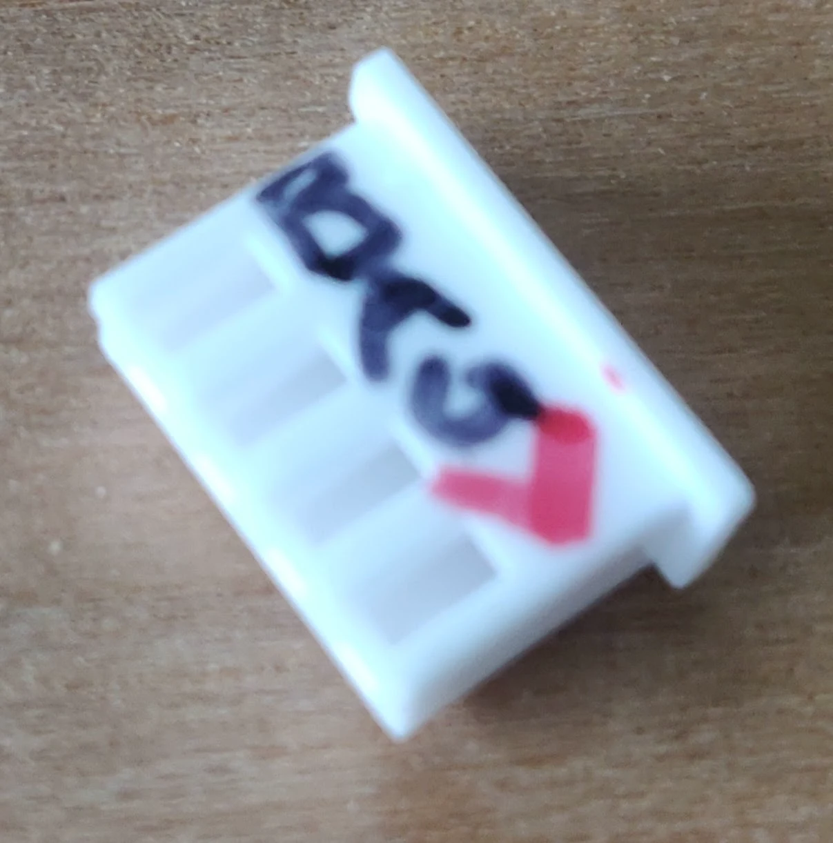 Photo creditelectrical/wiring/images/4p-JST.jpg JPL / California Institute of Technology and Open Source Rover contributors · Apache-2.0Resized without cropping and converted to WebP. |
|---|---|
| Dupont 4p connector. From top to bottom: VCC/5V (white) → GND (yellow) → enA (blue) → enB (green) | female 4p JST connector. From top to bottom: enB → enA → GND → VCC/5V |
| Finally insert the crimps into the connectors. Repeat for all cables, using the same coloring for each connector hole. If you used heat shrink, use a heat gun to secure the connection. |
Tip: When you finish a cable, use the connection testing setting on your multimeter so verify that your cables work. This will save you a lot of time debugging in the future!
Step (2) 4x: Dupont male 4pin ↔ 4-pins of female Molex connectors
These cables will connect the Dupont side of the cables we made in step (1) to the PCB via a 6pin PCI-E connector with female Molex connectors.
This process is very similar to the steps we did in (1), except we'll use male DuPont crimps on one side and female Molex crimps on the other side. For the male DuPont connector side, make sure the wires match the female DuPont connector you made in Step (1).
Grab the 2 pieces of encoder wire of 53cm and 2 pieces of 46cm and prepare the wire ends for crimping. Attach the crimps to each wire and repeat for each set of wires. As before, mark the connectors as in the images below, then insert the wires into the connectors.
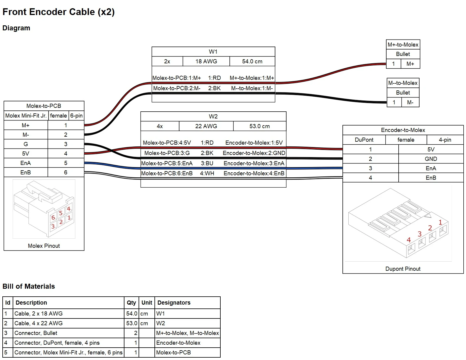
Photo credit
electrical/wiring/images/front_encoder.jpg
JPL / California Institute of Technology and Open Source Rover contributors · Apache-2.0Resized without cropping and converted to WebP.
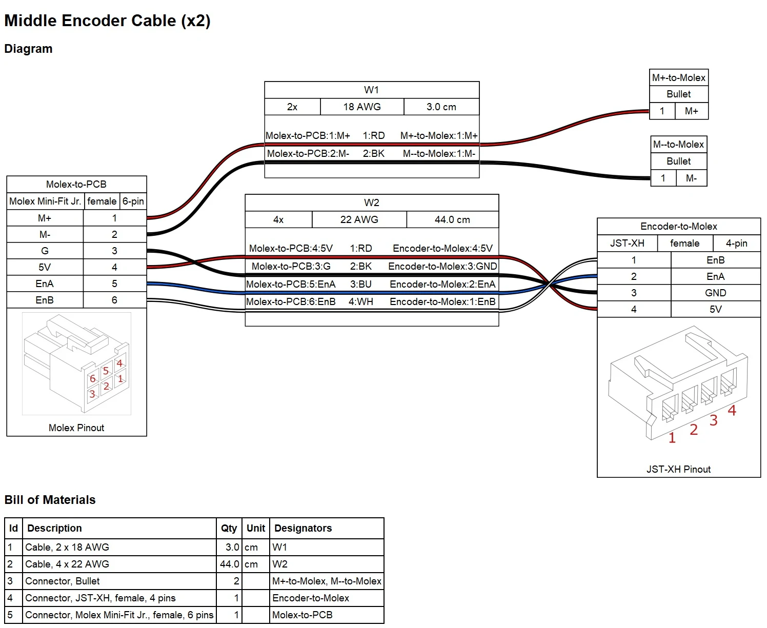
Photo credit
electrical/wiring/images/middle_encoder.jpg
JPL / California Institute of Technology and Open Source Rover contributors · Apache-2.0Resized without cropping and converted to WebP.
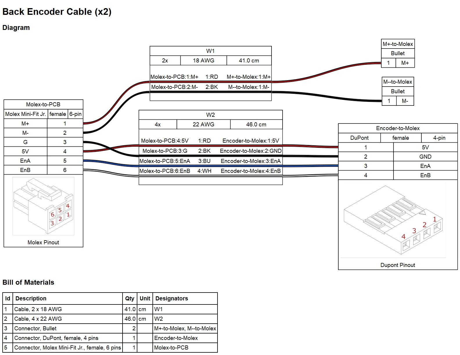
Photo credit
electrical/wiring/images/back_encoder.jpg
JPL / California Institute of Technology and Open Source Rover contributors · Apache-2.0Resized without cropping and converted to WebP.
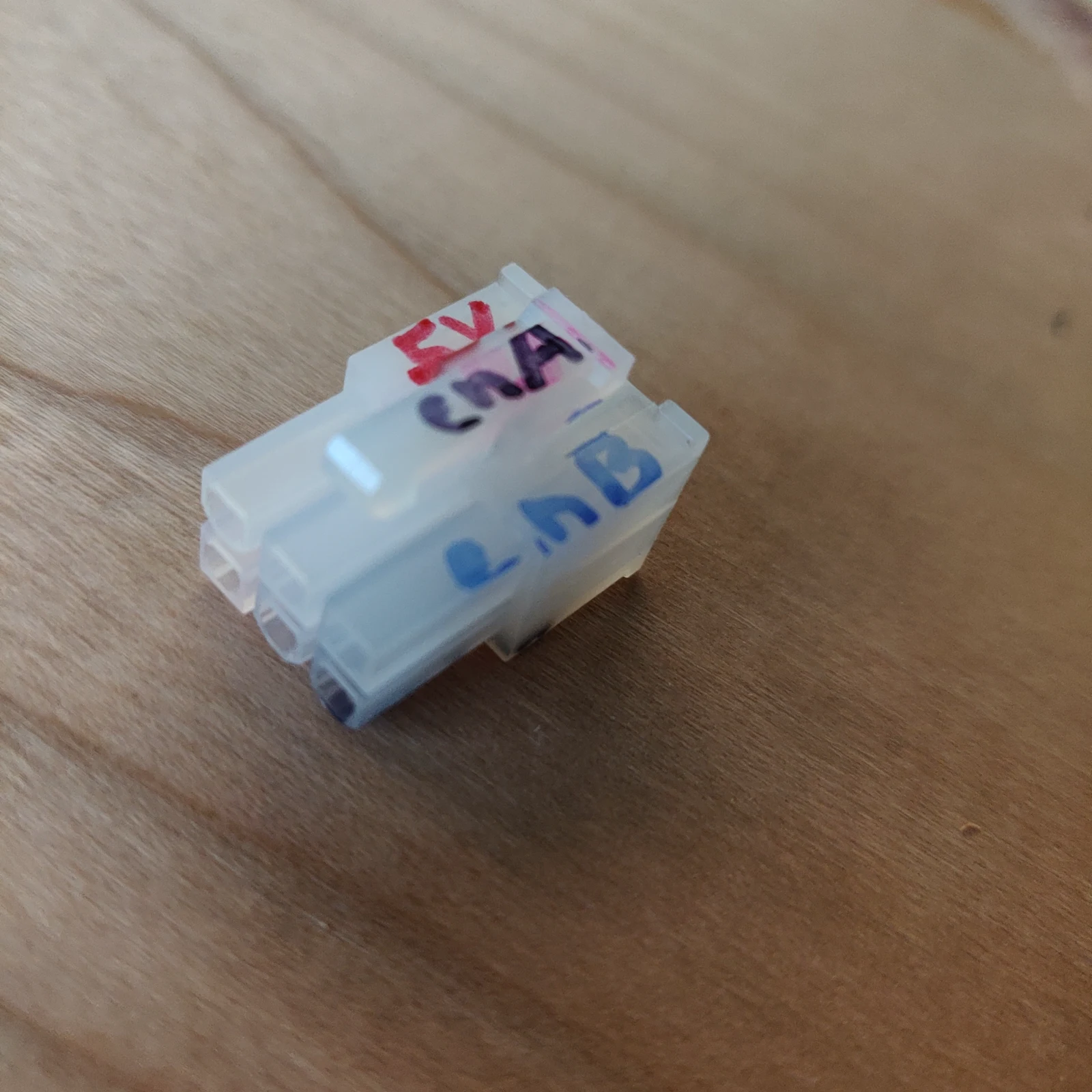 Photo creditelectrical/wiring/images/pcie-top.jpg JPL / California Institute of Technology and Open Source Rover contributors · Apache-2.0Resized without cropping and converted to WebP. | 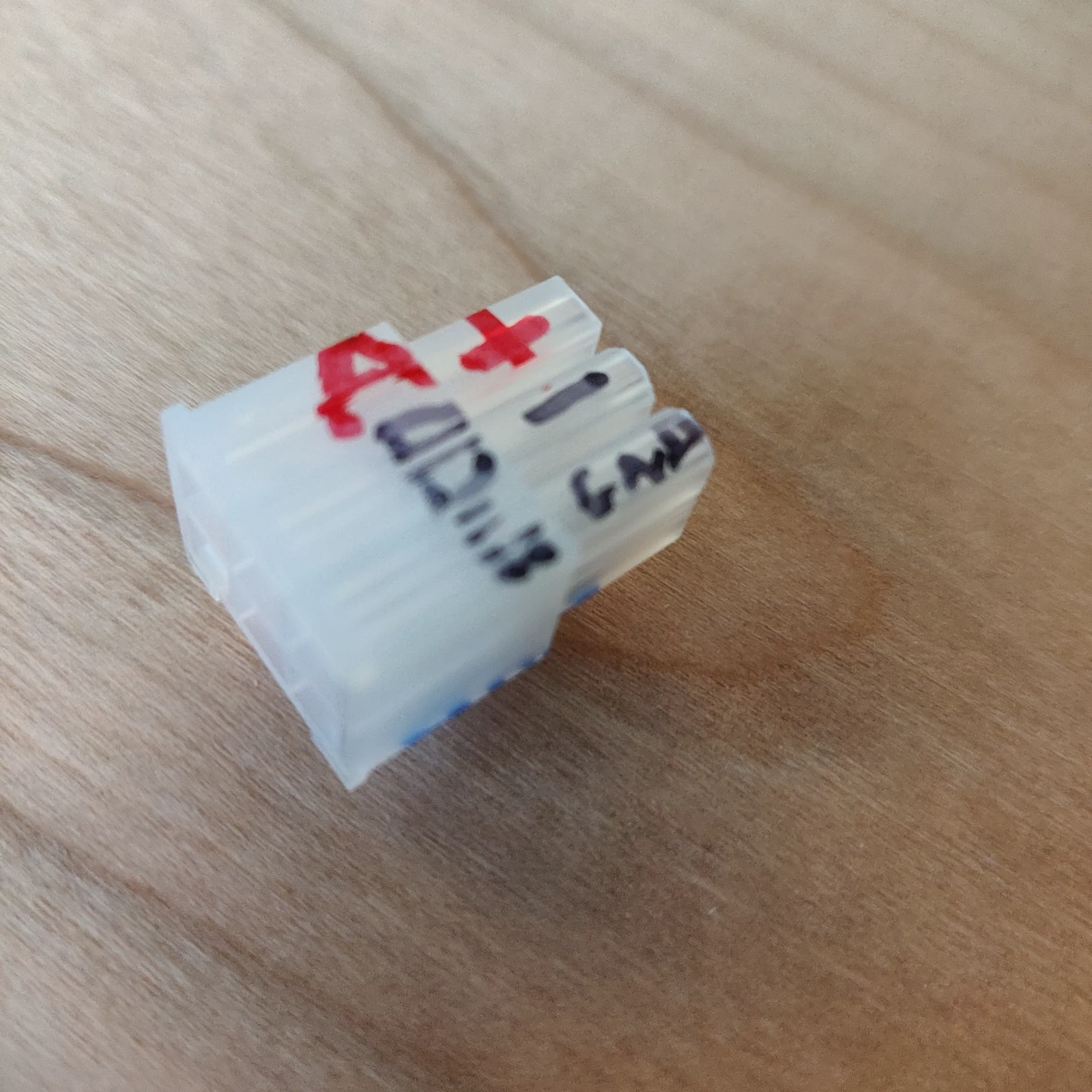 Photo creditelectrical/wiring/images/pcie-bottom.jpg JPL / California Institute of Technology and Open Source Rover contributors · Apache-2.0Resized without cropping and converted to WebP. |
|---|---|
| Top of PCI-E connector. 5V → enA → enB | bottom of PCI-E connector. M+/A → Mi/B → GND |
Mark the PCI-E connector with on each of the two longer cables with 'F' for front and the two connectors attached to the shorter cables with 'B' for back. This will prevent inserting the cables into the wrong slot on the PCB since all cables arrive into the body through the same goRail. The remaining two slots for M+ (A) and M- (B) on each of these connectors will be filled in step (4).
Step (3) 2x: JST female 4pin ↔ 4-pins of female Molex connectors
These 2 wires that connect the drive motor encoders for the middle wheels to the PCB directly are a combination of cables (1) and (2), skipping the intermediate DuPont connector. Mark the PCI-E connector for each of the two cables with 'M' for middle.
Step (4) 6x: 2-pin female bullet connector ↔ 2x female Molex connector
Grab the 6 pairs of red and black power wire. On each wire side attach a female bullet connector on one side and a female Molex connector on the other.
- For the two shortest cables you made, insert the Molex end into the open slots on the middle PCI-E connector you assembled in Step (3).
- For the two longest cables you made, insert the Molex end into the open slots on the front PCI-E connector you assembled in Step (2).
- For the two mid-length cables you made, insert the Molex end into the open slots on the back PCI-E connector you assembled in Step (2).
You now how all the wiring completed for the drive motors!
Step (5) 4x: Dupont male 3pin ↔ DuPont female 3pin connectors
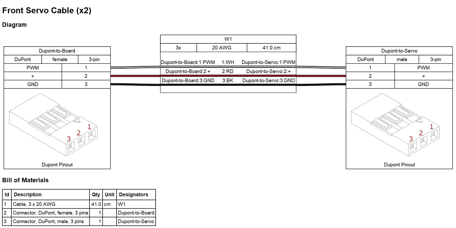
Photo credit
electrical/wiring/images/front_servo.jpg
JPL / California Institute of Technology and Open Source Rover contributors · Apache-2.0Resized without cropping and converted to WebP.
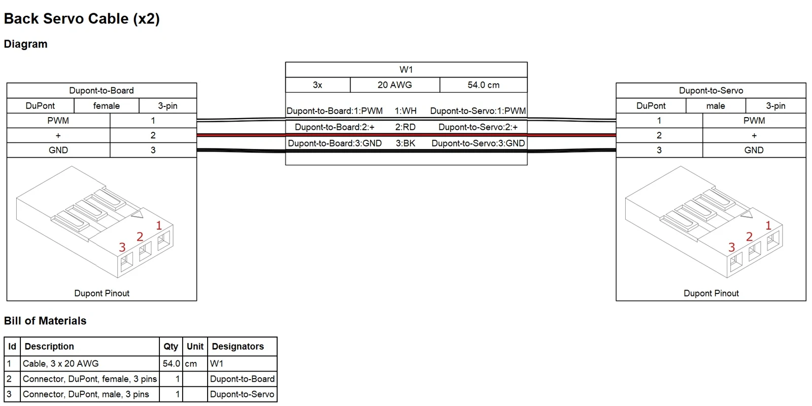
Photo credit
electrical/wiring/images/back_servo.jpg
JPL / California Institute of Technology and Open Source Rover contributors · Apache-2.0Resized without cropping and converted to WebP.
All that's left are the servo ribbon cables. The red and black wires are (+) and (-) voltage to the motor and the white cable carries the PWM signal to command the on-board controller to command the motor to the desired angle, using the built-in absolute encoder. The PCB header pins for the servo motors are wired in the same order (PWM, (+), (-)) so we're essentially building an extension cord in this step. One one side you'll be using male DuPont crimps while on the other you'll use female DuPont crimps. The connectors for both sides are identical.
You should now have 12 finished cable assemblies. Congratulations! Don't forget to make sure each connection is solid and tested before moving on.
Control Board Assembly, v2.0.3
The overall Control Board consists of a Motor Board with a Brain Board mounted on top. These are the instructions to assemble these two separate pcbs and mount them together as the unified control board.
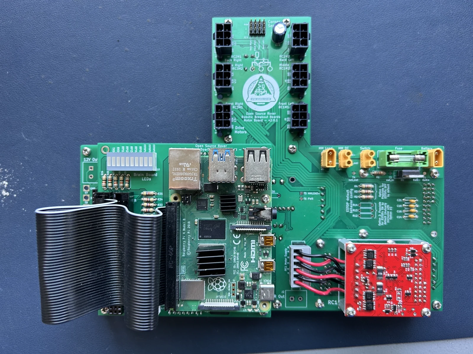
Photo credit
electrical/pcb/images/assembled/complete_pcb_top.jpg
JPL / California Institute of Technology and Open Source Rover contributors · Apache-2.0Resized without cropping and converted to WebP.
This document goes through the process of assembling and testing the custom Printed Circuit Boards for the project.
Note that the images in these instructions are taken from an assembly of the v2.0.1 board. There are minimal differences between v2.0.1 and v2.0.3 - such that it wasn't worth doing another photoshoot for v2.0.3. Make sure to follow the written instructions when in doubt.
Table of Contents
- Part References
- Schematic and Layout Documentation
- Motor Board Assembly
- Brain Board Assembly
- Motor Board and Brain Board Mating
- Testing the PCB and wiring for the Drive Motors
1. Part References
Check out the BOM documents
All parts referenced in these instructions use the schematic "reference designator" from the silk screen on the pcbs. E.g. "C1", "J2", and "R28". You should look up the details of these parts within the v2.0.3 BOM the board ref parts spreadsheet or the v2.0.3 BOM other parts spreadsheet. This will tell you the unique ID of the part that we use for ordering from Digikey + elsewhere, and will also link to pictures of the part on the relevant website.
Generally these instructions have enough images to clearly show and identify the parts, but whenever in doubt the best thing to do is to look up the reference in the BOM spreadsheet.
2. Schematic and Layout Documentation
You can see the KiCAD files in the repo, or see documentation of both the schematics (how all the electrical parts logically connect to one another) and the layout (how the parts are physically placed on the boards) in the control_board/documentation directory. The documentation directory contains:
- control_board/documentation/3d_images - renderings of each of the two boards
- control_board/documentation/layout - SVG files of each layer individually and of the entire board, for both boards.
- control_board/documentation/schematics.pdf - schematics as a PDF
For notes on why the schematic is drawn the way it is -- KiCad power-port and PWR_FLAG conventions, the reference-designator policy when revving the board, and per-component notes on the LM358, Roboclaw, RPi, regulators, INA260 and PCA9685 -- see control_board/README_schematic.md.
3. Motor Board Assembly
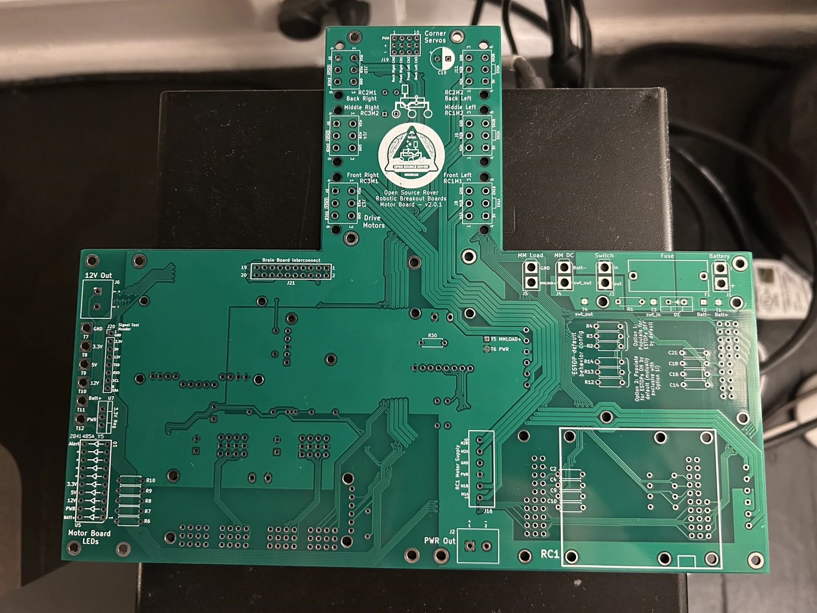 Photo creditelectrical/pcb/images/assembly/bare_board.jpg JPL / California Institute of Technology and Open Source Rover contributors · Apache-2.0Resized without cropping and converted to WebP. 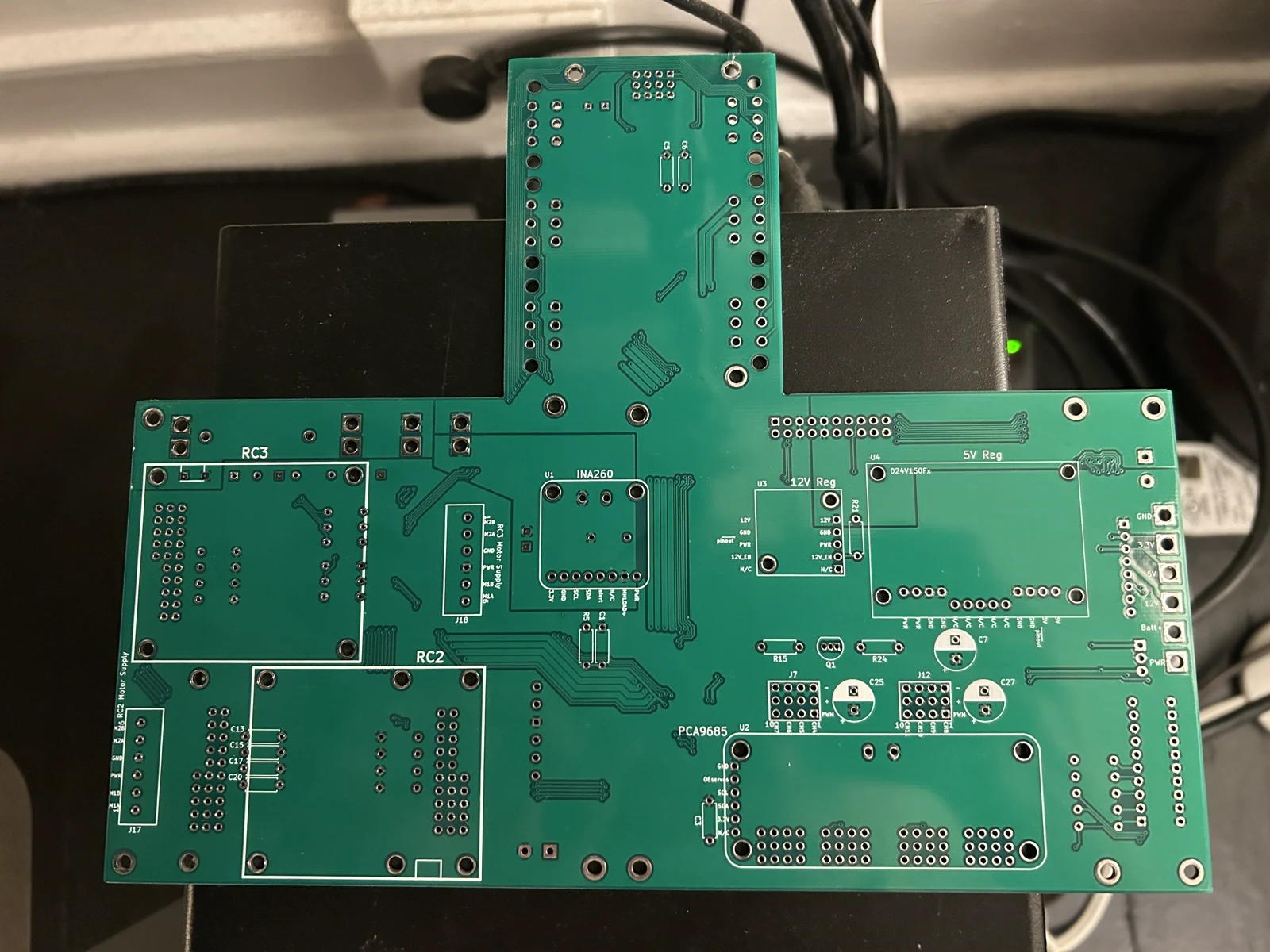 Photo creditelectrical/pcb/images/assembly/bare_board_bottom.jpg JPL / California Institute of Technology and Open Source Rover contributors · Apache-2.0Resized without cropping and converted to WebP. |
|---|
| Figure 3.0: front (left) and back (right) of motor board |
3.1 Attach standoffs
Attach M2.5 x 30mm standoffs to the bare board, for ease of future soldering work.
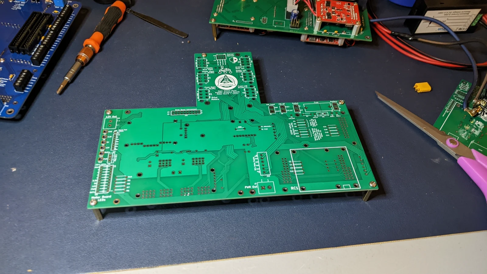 Photo creditelectrical/pcb/images/assembly/PXL_20230413_052035126.jpg JPL / California Institute of Technology and Open Source Rover contributors · Apache-2.0Resized without cropping and converted to WebP. 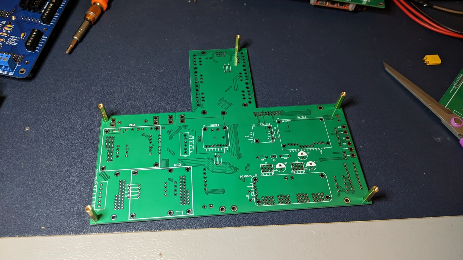 Photo creditelectrical/pcb/images/assembly/PXL_20230413_052039855.jpg JPL / California Institute of Technology and Open Source Rover contributors · Apache-2.0Resized without cropping and converted to WebP. |
|---|
| Figure 3.1: Standoffs attached |
3.2 Solder on power headers and fuse holder
Solder on the XT30 headers for footprints J1, J3, J4, and J5, as well as the fuse holder F1.
Make sure to choose the proper XT30 header for the corresponding J footprint:
- J1: male
- J3: female
- J4: female
- J5: male See the images to clarify which one is which.
The pins on the XT30 will be slightly smaller than the holes on the board - this is fine, just make sure to use a lot of solder to connect them so there's a good mechanical connection. The soldering should be fairly straightforward once you start.
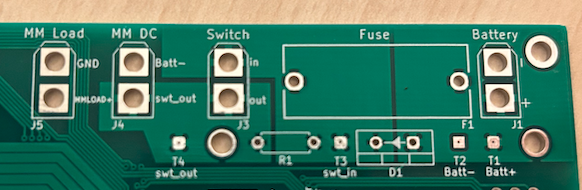 Photo creditelectrical/pcb/images/assembly/power_headers.png JPL / California Institute of Technology and Open Source Rover contributors · Apache-2.0Unmodified source image. |
|---|
| Figure 3.2: Power headers + fuse holder footprints |
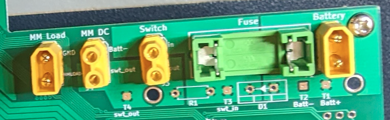 Photo creditelectrical/pcb/images/assembly/power_headers_attached.png JPL / California Institute of Technology and Open Source Rover contributors · Apache-2.0Unmodified source image. |
|---|
| Figure 3.3: Power headers + fuse holder attached |
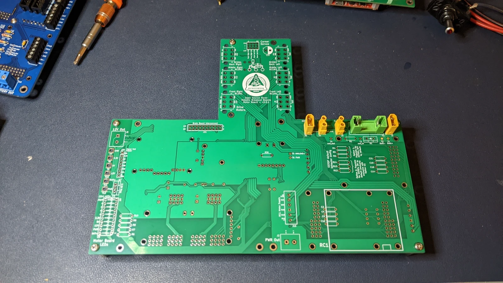 Photo creditelectrical/pcb/images/assembly/PXL_20230413_052422615.jpg JPL / California Institute of Technology and Open Source Rover contributors · Apache-2.0Resized without cropping and converted to WebP. |
|---|
| Figure 3.4: Power headers and fuse holder attached, zoomed out |
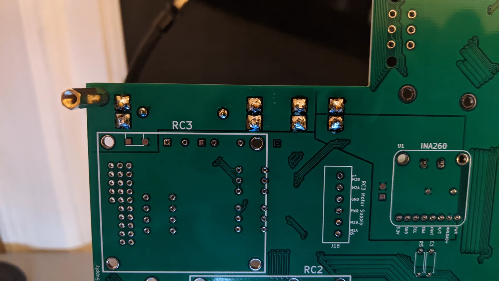 Photo creditelectrical/pcb/images/assembly/PXL_20230413_054441445.jpg JPL / California Institute of Technology and Open Source Rover contributors · Apache-2.0Resized without cropping and converted to WebP. |
|---|
| Figure 3.5: Close up view of soldered footprints for headers |
3.3 Solder resistor R1 and power diode D1
Make sure to attach D1 in the correct orientation!
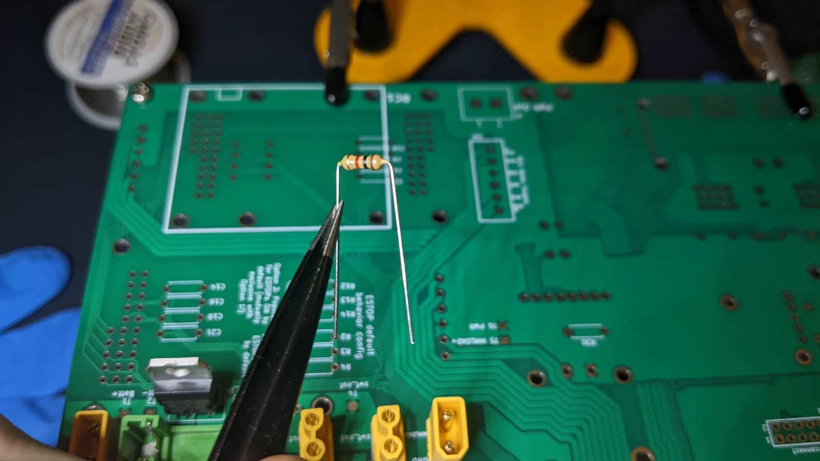 Photo creditelectrical/pcb/images/assembly/PXL_20230413_054943541.jpg JPL / California Institute of Technology and Open Source Rover contributors · Apache-2.0Resized without cropping and converted to WebP. |
|---|
| Figure 3.6: Resistor R1 |
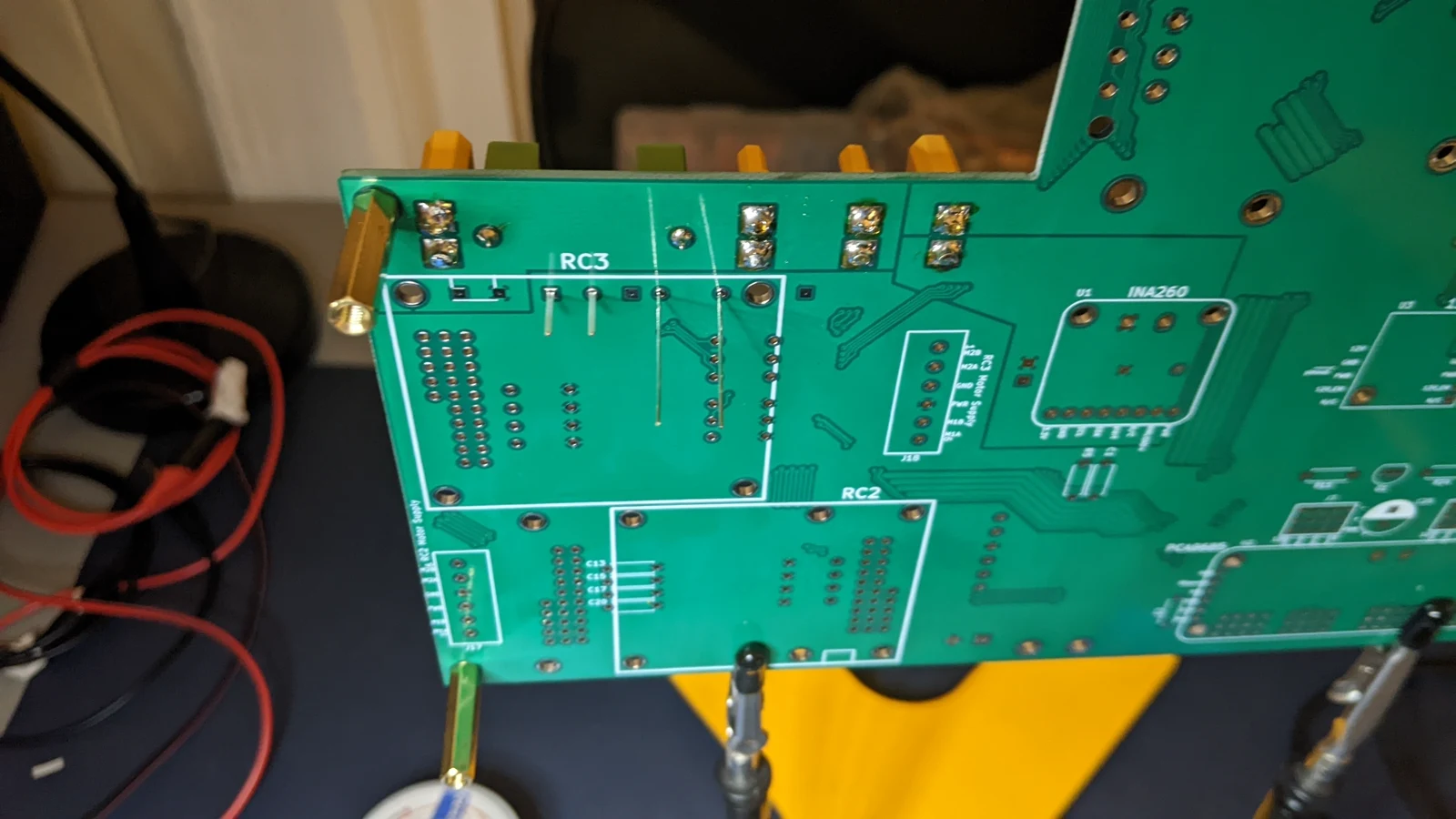 Photo creditelectrical/pcb/images/assembly/PXL_20230413_055134872.MP.jpg JPL / California Institute of Technology and Open Source Rover contributors · Apache-2.0Resized without cropping and converted to WebP. |
|---|
| Figure 3.7: Through hole leads for R1 and D1 |
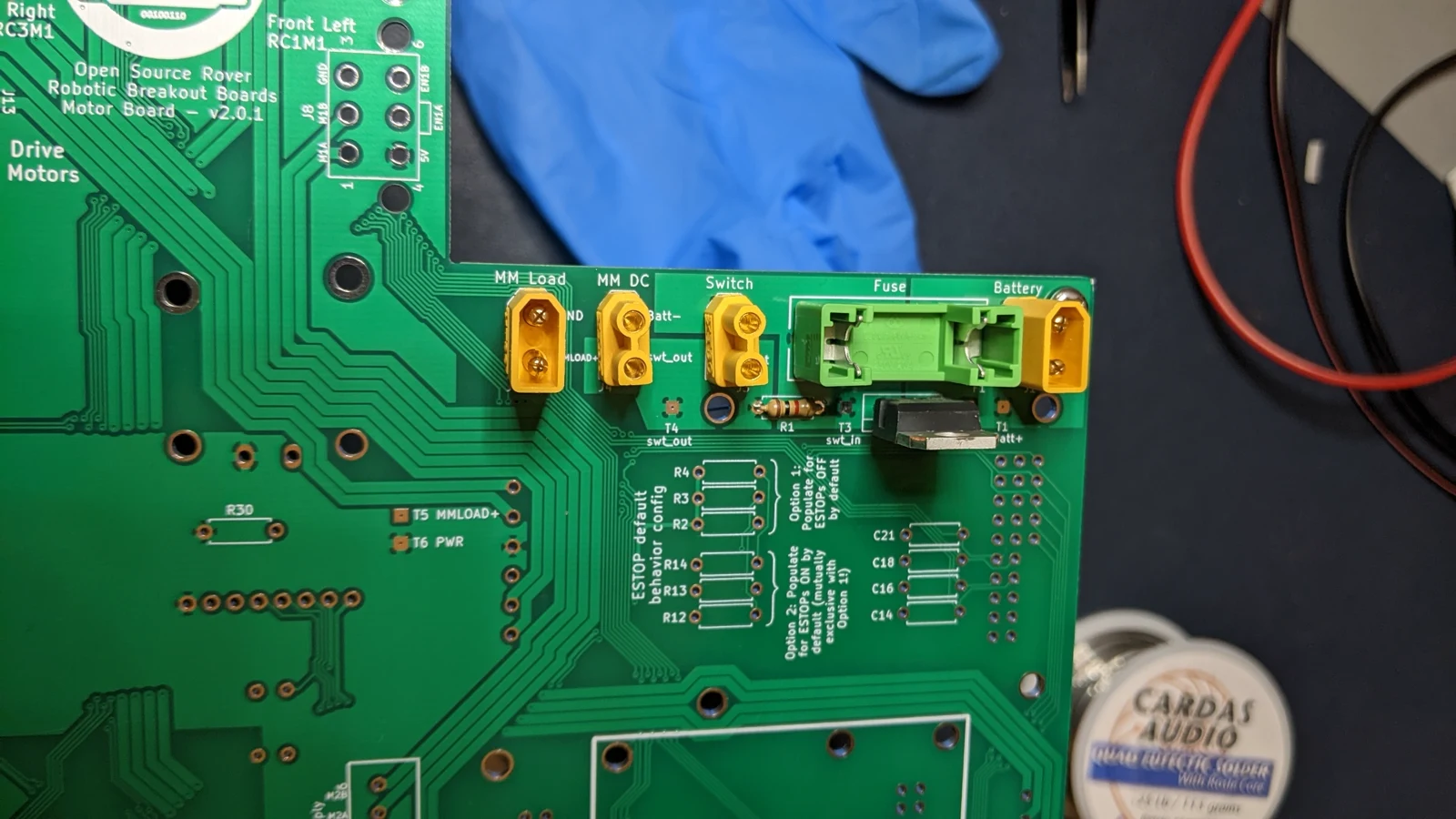 Photo creditelectrical/pcb/images/assembly/PXL_20230413_055558226.jpg JPL / California Institute of Technology and Open Source Rover contributors · Apache-2.0Resized without cropping and converted to WebP. |
|---|
| Figure 3.8: R1 and D1 attached |
3.4 Test the power connectors
Insert a fuse (part# B1) into the fuse holder (as shown in Figure 3.8 below)
Using the appropriate matching XT30 connectors, connect the power headers to a power supply (or your battery), the main external power switch (part# B9), and the multimeter (part# B10)
Use these diagrams to determine how to wire things together:
When testing with a power supply, provide 14.8V DC and current limit to 1.0A. Just to the left of the main fuse is a XT30 connector labeled "Switch" – this if for the main on/off toggle switch. The XT30 connectors labeled MM Load and MM DC connect to the multimeter box.
[!Note] If you have already installed capacitors on the board, it is normal for power header J5 (MM Load) to briefly beep for less than a second when testing for continuity after soldering the power headers. This occurs because the capacitors momentarily charge. This behavior is expected and does not indicate a short circuit.
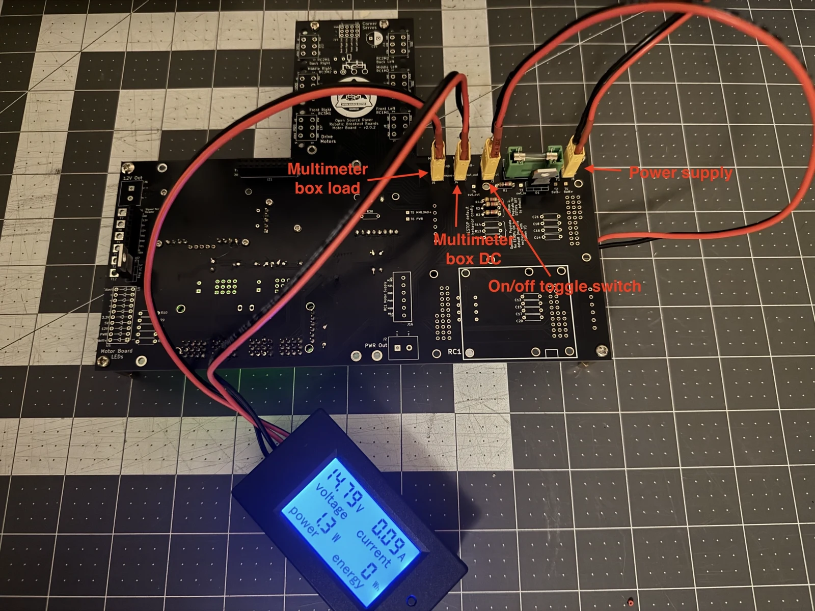 Photo creditelectrical/pcb/images/assembly/controlboard-power-headers.jpeg JPL / California Institute of Technology and Open Source Rover contributors · Apache-2.0Resized without cropping and converted to WebP. |
|---|
| Figure 3.9: Power headers connected to the power supply, on/off toggle switch (out of view under the PCB) and multimeter box. |
After testing, make sure to disconnect the power supply.
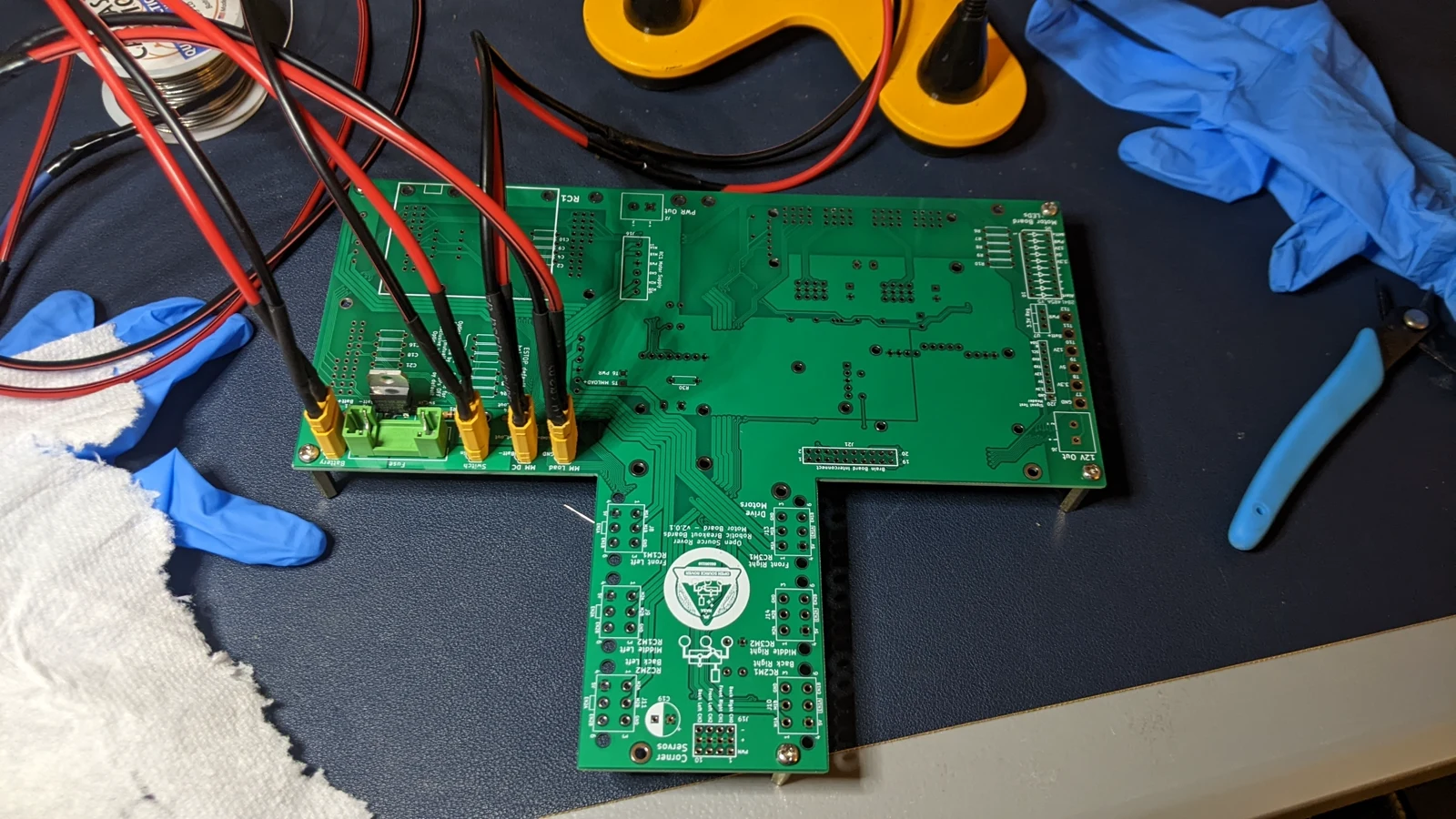 Photo creditelectrical/pcb/images/assembly/PXL_20230413_061454863.jpg JPL / California Institute of Technology and Open Source Rover contributors · Apache-2.0Resized without cropping and converted to WebP. |
|---|
| Figure 3.10: Wires connected to power headers |
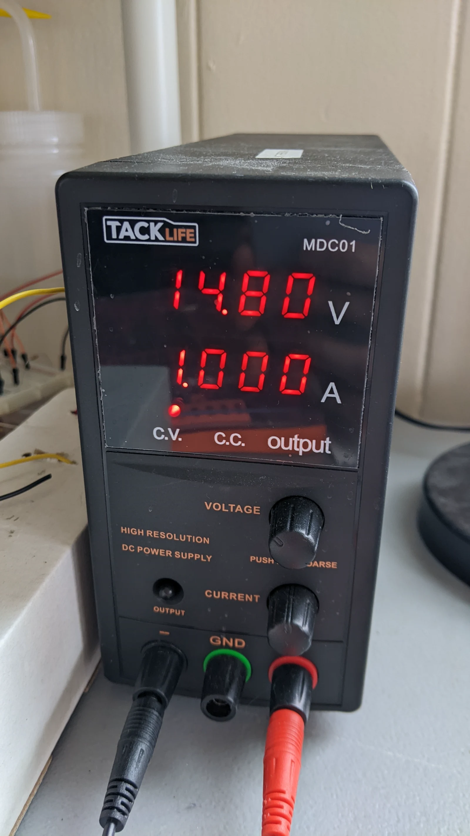 Photo creditelectrical/pcb/images/assembly/PXL_20230416_234516660.jpg JPL / California Institute of Technology and Open Source Rover contributors · Apache-2.0Resized without cropping and converted to WebP. |
|---|
| Figure 3.11: Power supply providing 14.8V DC and current limited to 1.0A |
Use a multimeter to test the voltage between test points T4 ("swt_out") and T2 ("Batt-"). This should read the same value as input from the power supply/battery (14.8V)
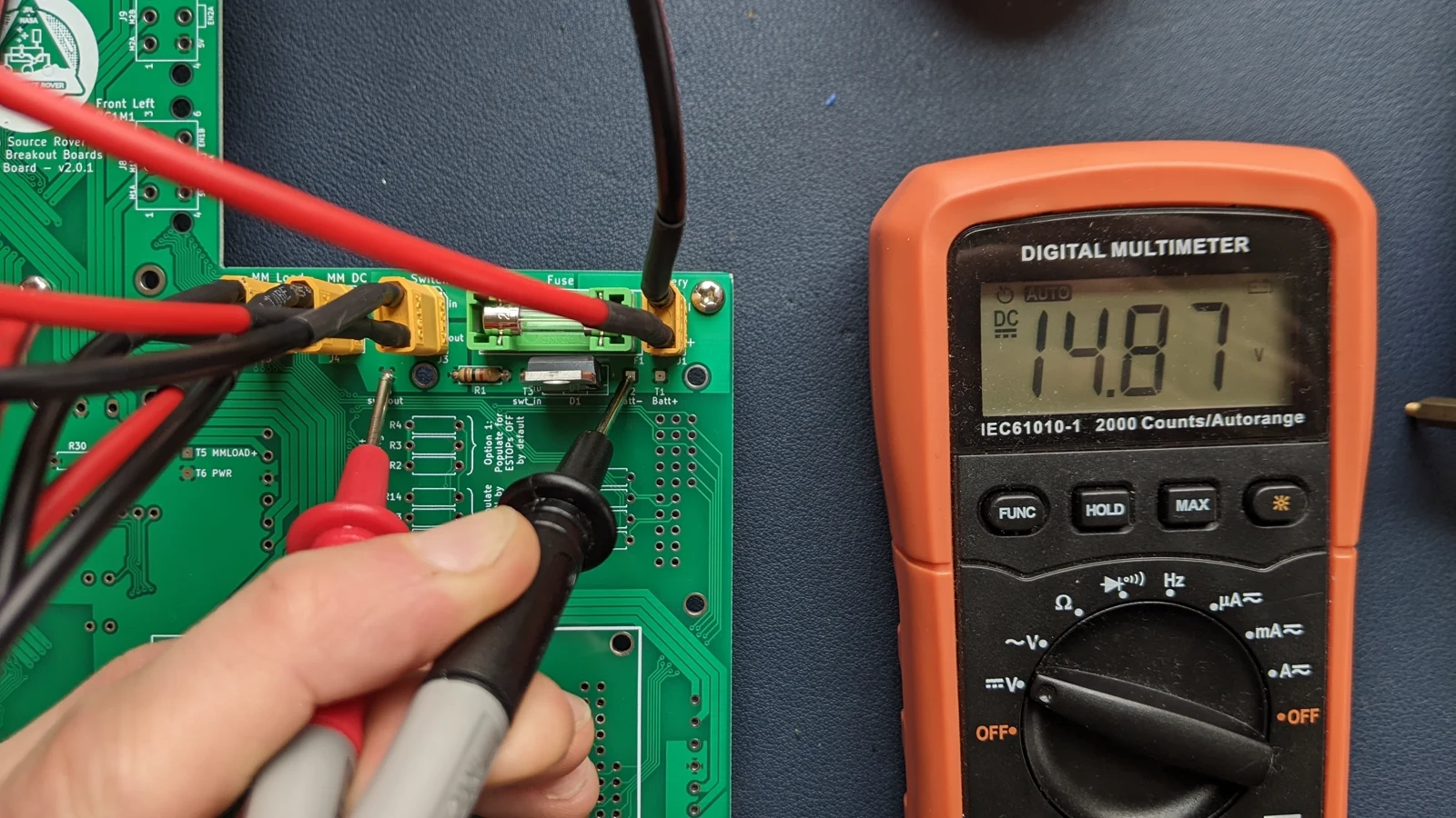 Photo creditelectrical/pcb/images/assembly/PXL_20230416_234547696.jpg JPL / California Institute of Technology and Open Source Rover contributors · Apache-2.0Resized without cropping and converted to WebP. |
|---|
| Figure 3.12: Testing the voltage between T4 and T2 |
Also check the voltage shown by the multimeter. This should show the same voltage as well.
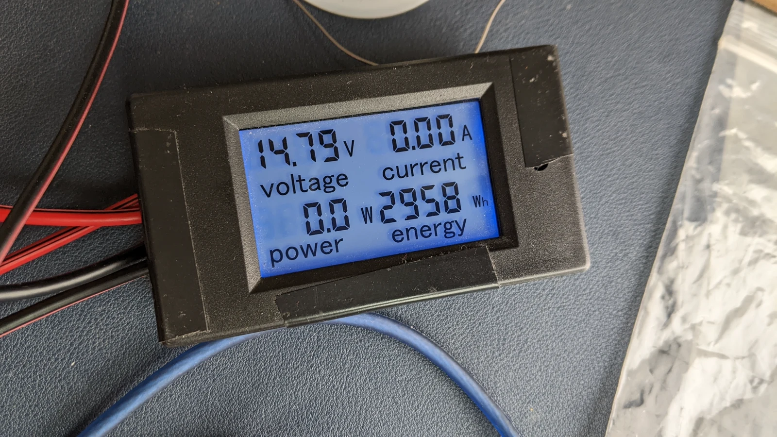 Photo creditelectrical/pcb/images/assembly/PXL_20230416_234553055.jpg JPL / California Institute of Technology and Open Source Rover contributors · Apache-2.0Resized without cropping and converted to WebP. |
|---|
| Figure 3.13: Testing the power input to the multimeter |
3.5 Install the INA 260
:exclamation: Before continuing, make sure to disconnect the power supply from the previous step! You should not have the board powered on while installing components. :exclamation:
The INA260 daughter board is used for digital sensing of voltage and current, measurements that the raspberry pi can query over an I2C connection. Unfortunately, it can be hard to find these INA260 parts nowadays - if you can't find one you will need to bypass U1, because it is in the path of the battery positive side supply.
Option 1: If you have an INA260 daughter board, you should install that in footprint U1 on the bottom side of the motor board.
See control_board/README_schematic.md for part numbers for inter-board pins and sockets.
- Attach 8x1 female header sockets to the eight pads on the bottom side of the INA260 / U1 footprint, as seen in Figure 3.14. This is sensing the current on the high side of the power, so PWR on the the Motor Board is connected to Vin+ on the INA260, and Vin- on the INA260 is connected to MMLOAD+, which connects to the main power bus of the rover.
- Attach 3x1 female header socket (cut from a longer Nx1 header) to the two pads on the bottom side of the INA260 / U1 footprint, as seen in Figure 3.14. You'll need to manually remove the center pin, as there is no hole/pad on the brain board.
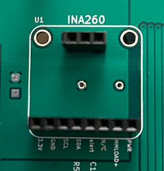 Photo creditelectrical/pcb/images/assembly/ina260_headers.png JPL / California Institute of Technology and Open Source Rover contributors · Apache-2.0Unmodified source image. |
|---|
| Figure 3.14: Sockets on U1 footprint installed |
- Attach 8x1 male header pins to the underside of the INA260, as seen in Figure 3.15
- Remove the center pin from a 3x1 male header pins, and solder to the INA260.
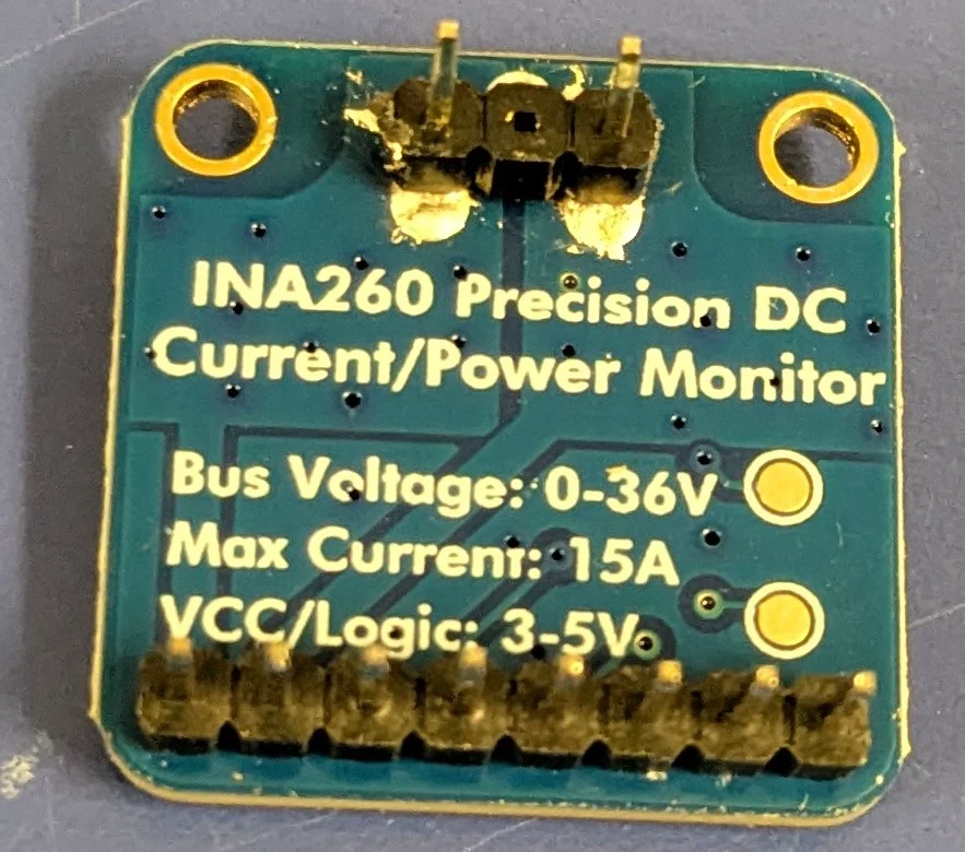 Photo creditelectrical/pcb/images/assembly/INA260_Bottom.jpg JPL / California Institute of Technology and Open Source Rover contributors · Apache-2.0Resized without cropping and converted to WebP. 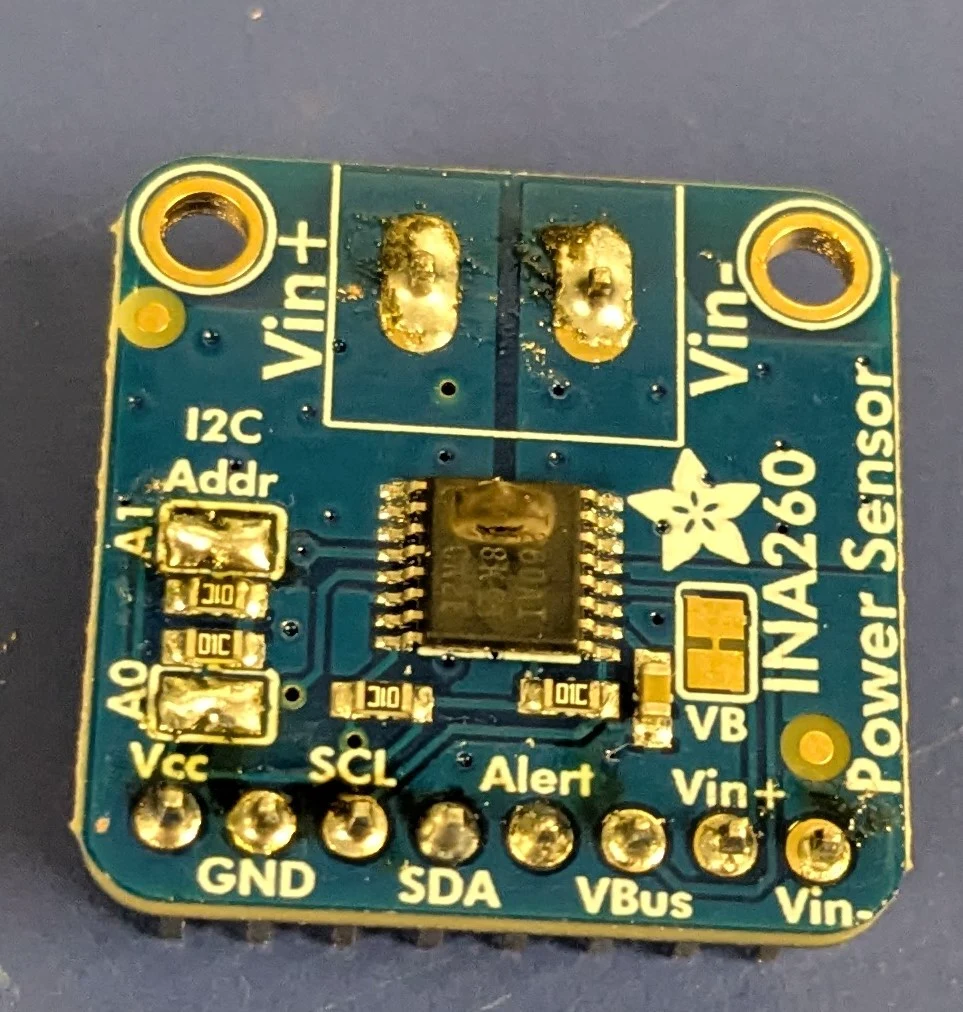 Photo creditelectrical/pcb/images/assembly/INA260_Top.jpg JPL / California Institute of Technology and Open Source Rover contributors · Apache-2.0Resized without cropping and converted to WebP. |
|---|
| Figure 3.15: INA260 Pins installed |
- Solder across pads A0 and A1 on the INA260 (to set it to use I2C Address 0x45)
- Insert the INA260 male pins into the U1 female sockets, as shown in Figure 3.16
- Optionally, install M2.5 x 12mm + 6mm standoffs between the motor board and the INA260.
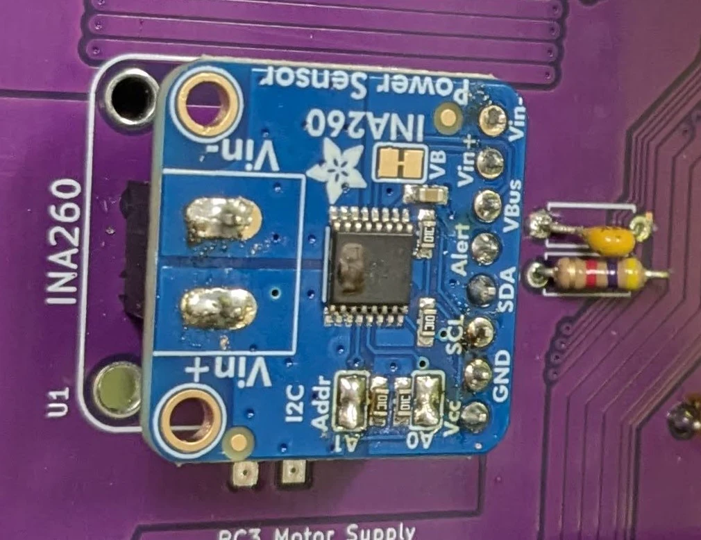 Photo creditelectrical/pcb/images/assembly/INA260_Installed.jpg JPL / California Institute of Technology and Open Source Rover contributors · Apache-2.0Resized without cropping and converted to WebP. |
|---|
| Figure 3.16: Headers on INA260 installed |
Option 2: If you don't have one, you will need to bypass U1
If you don't have an INA260, simply install a 0 ohm resistor (or a wire) in footprint R30, on the top side of the board, as shown in Figure 3.17.
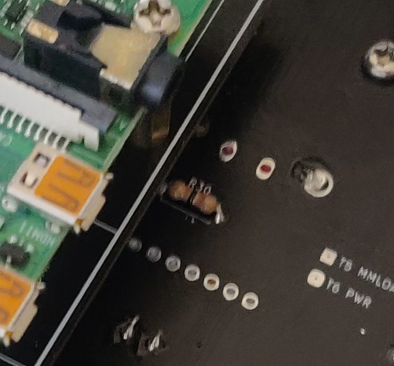 Photo creditelectrical/pcb/images/assembly/ina260_bypass.jpg JPL / California Institute of Technology and Open Source Rover contributors · Apache-2.0Resized without cropping and converted to WebP. |
|---|
| Figure 3.17: INA260 bypassed |
3.6 Install 5V bus regulator
This is the power regulator for the 5V line, which powers all the motors.
Install 3 female headers for the daughter board, into U4. You will need a two 4x1's, and a 5x1.
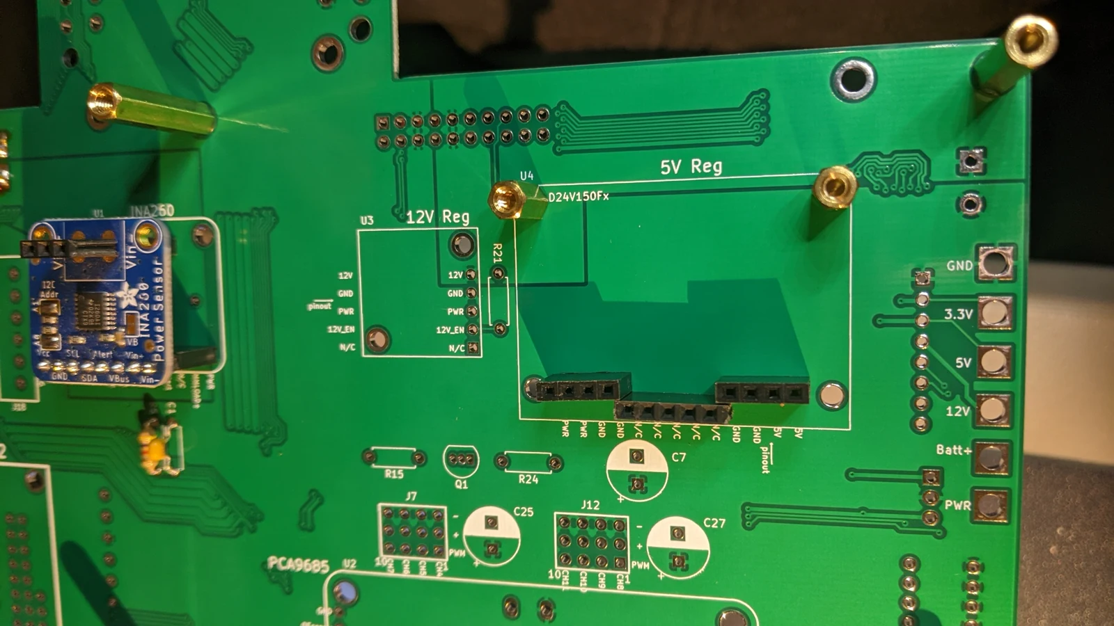 Photo creditelectrical/pcb/images/assembly/PXL_20230418_044902463.MP.jpg JPL / California Institute of Technology and Open Source Rover contributors · Apache-2.0Resized without cropping and converted to WebP. |
|---|
| Figure 3.18: 5V regulator headers installed |
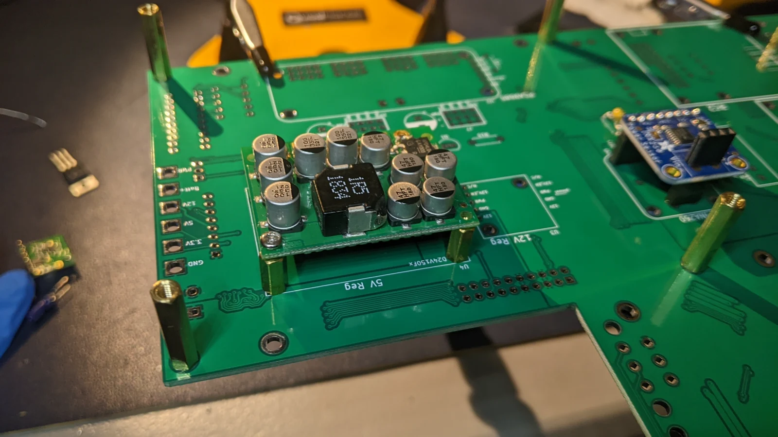 Photo creditelectrical/pcb/images/assembly/PXL_20230418_044810169.jpg JPL / California Institute of Technology and Open Source Rover contributors · Apache-2.0Resized without cropping and converted to WebP. |
|---|
| Figure 3.19: 5V regulator installed |
3.7 Install 12V bus regulator U3
Solder a 5x1 female header to the U3 footprint, and attach M2.5 x 10mm standoffs between the regulator and motor board
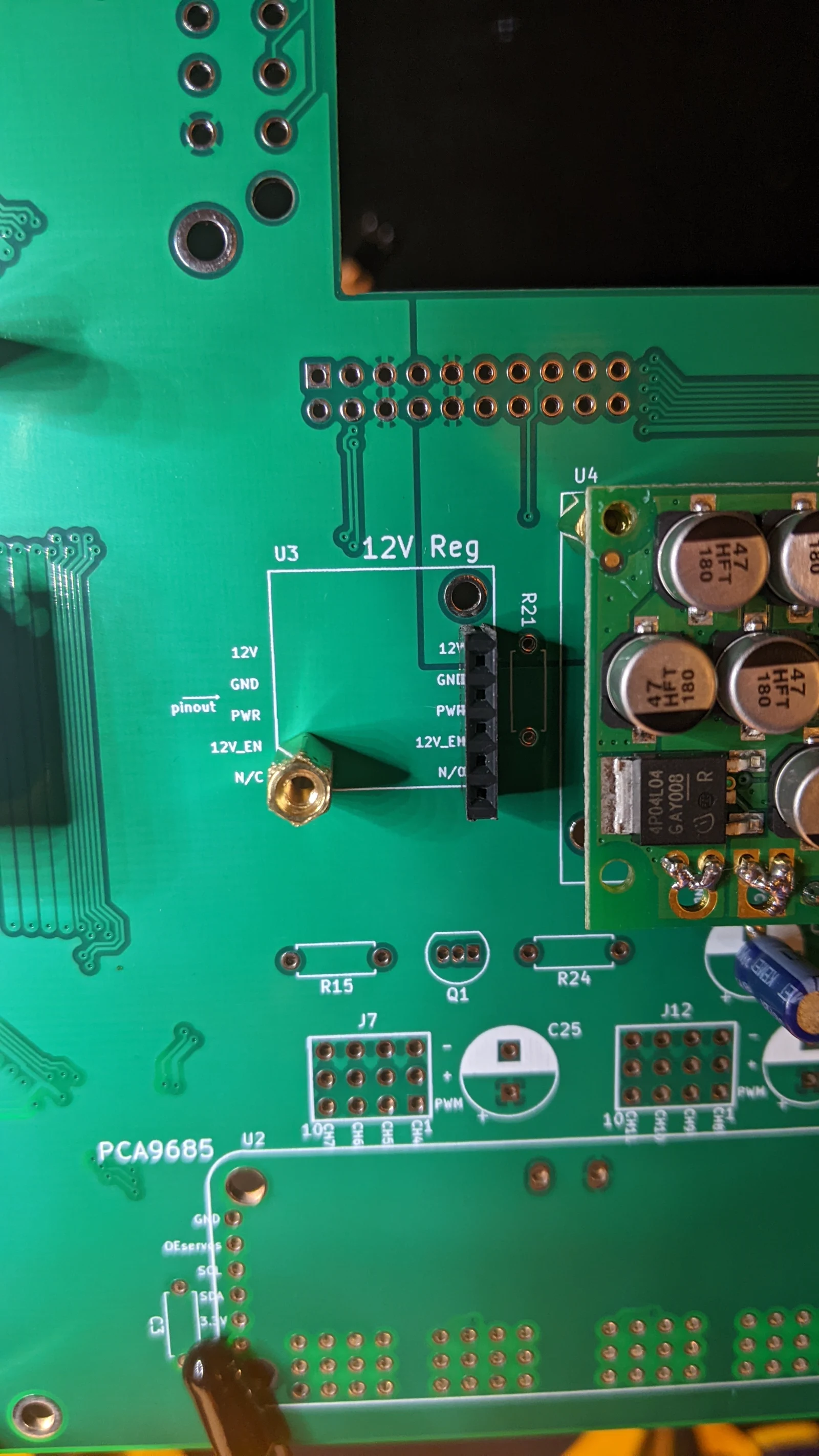 Photo creditelectrical/pcb/images/assembly/PXL_20230418_050503408.jpg JPL / California Institute of Technology and Open Source Rover contributors · Apache-2.0Resized without cropping and converted to WebP. |
|---|
| Figure 3.20: U3 footprint |
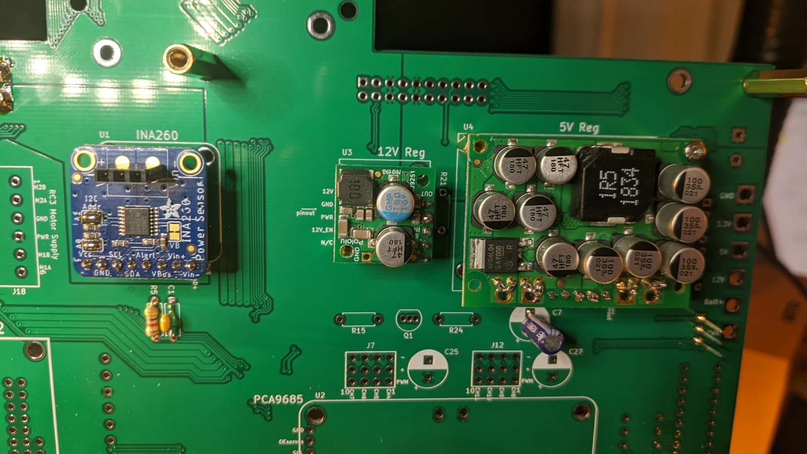 Photo creditelectrical/pcb/images/assembly/PXL_20230418_051040927.jpg JPL / California Institute of Technology and Open Source Rover contributors · Apache-2.0Resized without cropping and converted to WebP. |
|---|
| Figure 3.21: 12v regulator installed |
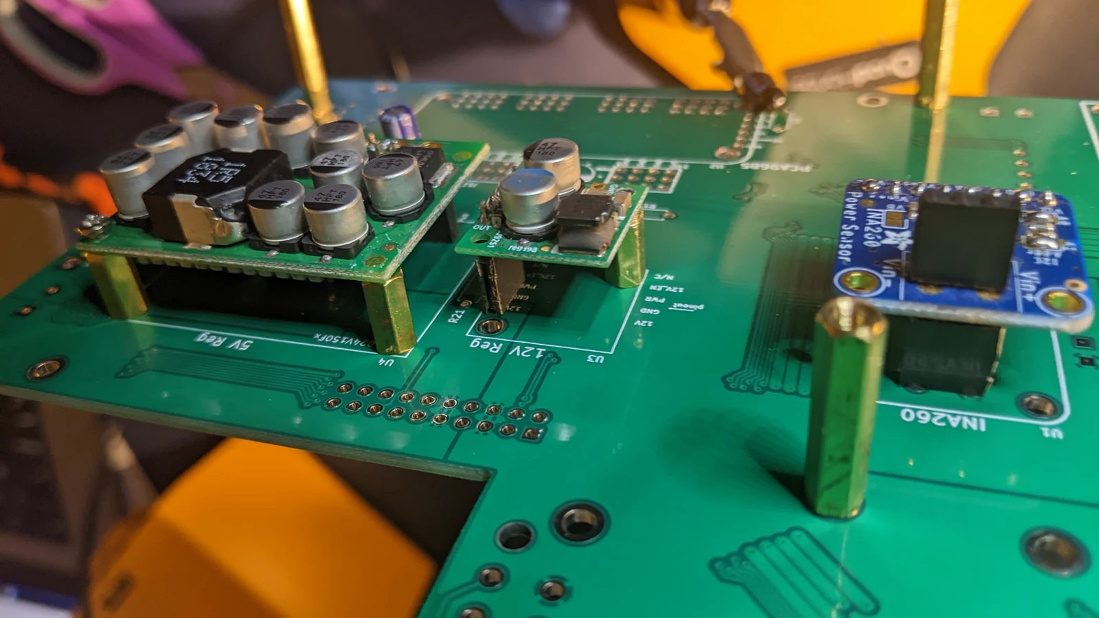 Photo creditelectrical/pcb/images/assembly/PXL_20230418_051046001.MP.jpg JPL / California Institute of Technology and Open Source Rover contributors · Apache-2.0Resized without cropping and converted to WebP. |
|---|
| Figure 3.22: 12v regulator installed (2) |
3.8 Install 3.3V bus regulator U7 and decoupling capacitor C7
The 3.3V bus regulator is a linear voltage regulator and is physically much smaller - it comes in the same packaging as diode D1. Make sure to install the regulator in the correct direction as shown in Figure 3.24.
Capacitor C7 is the decoupling capacitor for the 3.3v bus. Make sure to install C7 in the proper direction, as shown in Figure 3.25. One side of the capacitor has negative polarity indicators on it, that should be installed opposite the "+" sign on the footprint.
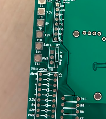 Photo creditelectrical/pcb/images/assembly/u7_bare.png JPL / California Institute of Technology and Open Source Rover contributors · Apache-2.0Unmodified source image. |
|---|
| Figure 3.23: U7 footprint |
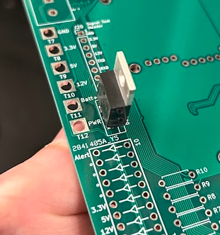 Photo creditelectrical/pcb/images/assembly/u7_installed.png JPL / California Institute of Technology and Open Source Rover contributors · Apache-2.0Unmodified source image. |
|---|
| Figure 3.24: 3.3v regulator installed in U7 |
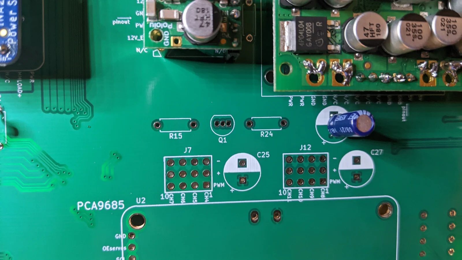 Photo creditelectrical/pcb/images/assembly/PXL_20230418_051556901.MP.jpg JPL / California Institute of Technology and Open Source Rover contributors · Apache-2.0Resized without cropping and converted to WebP. |
|---|
| Figure 3.25: Capacitor C7 installed |
3.9 Install resistors R15, R24, and BJT transistor Q1
These form the circuit for the alert signal LED logic.
Photo creditelectrical/pcb/images/assembly/PXL_20230418_051556901.MP.jpg JPL / California Institute of Technology and Open Source Rover contributors · Apache-2.0Resized without cropping and converted to WebP. |
|---|
| Figure 3.26: R15, R24, and Q1 footprints |
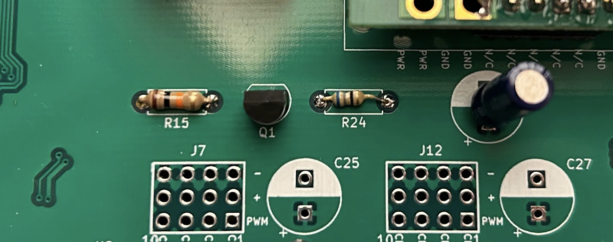 Photo creditelectrical/pcb/images/assembly/alert_led_components.png JPL / California Institute of Technology and Open Source Rover contributors · Apache-2.0Unmodified source image. |
|---|
| Figure 3.27: R15, R24, and Q1 installed |
3.10 Test all voltage lines
Test all the power buses/voltage lines using the test points on the far left side of the top side of the board (T7 through T12).
The silk screen right of each hole indicates what voltage each test point should be at.
- First, connect the power supply to your board and provide 14.8v (see step 3.4)
- then, use the multimeter to test the voltage at each test point
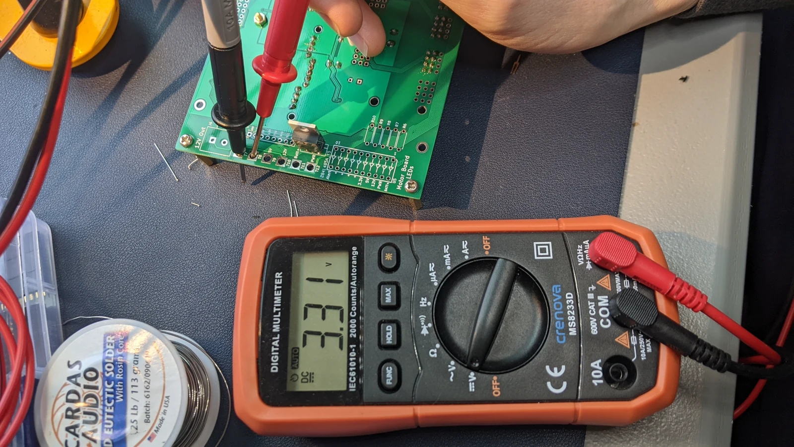 Photo creditelectrical/pcb/images/assembly/PXL_20230424_003614642.jpg JPL / California Institute of Technology and Open Source Rover contributors · Apache-2.0Resized without cropping and converted to WebP. |
|---|
| Figure 3.28: testing the 3.3v bus |
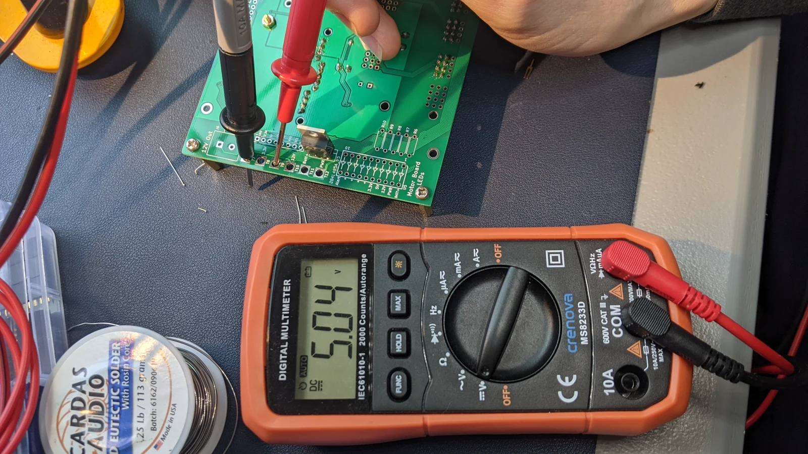 Photo creditelectrical/pcb/images/assembly/PXL_20230424_003617280.jpg JPL / California Institute of Technology and Open Source Rover contributors · Apache-2.0Resized without cropping and converted to WebP. |
|---|
| Figure 3.29: testing the 5v bus |
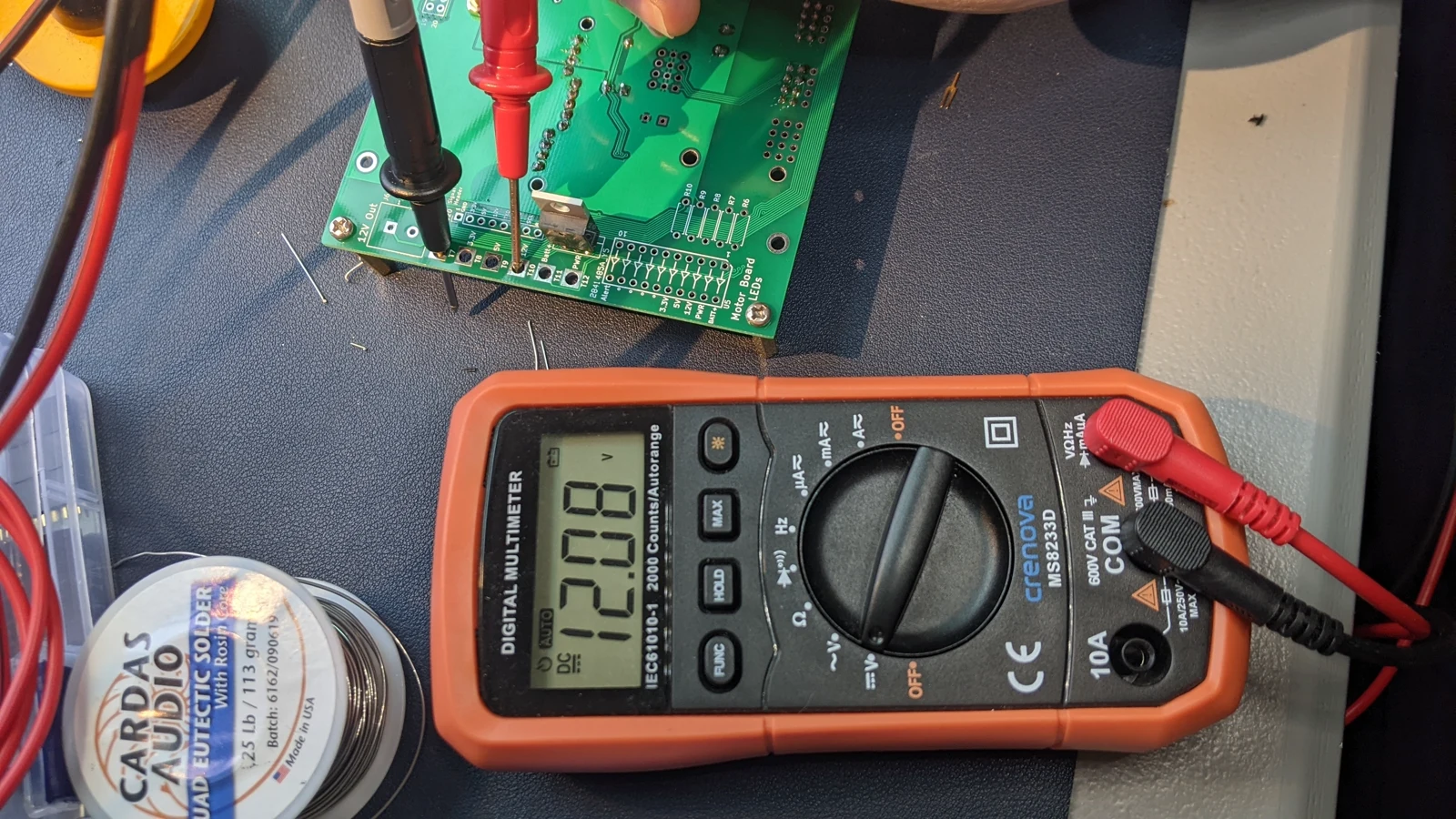 Photo creditelectrical/pcb/images/assembly/PXL_20230424_003620439.jpg JPL / California Institute of Technology and Open Source Rover contributors · Apache-2.0Resized without cropping and converted to WebP. |
|---|
| Figure 3.30: testing the 12v bus |
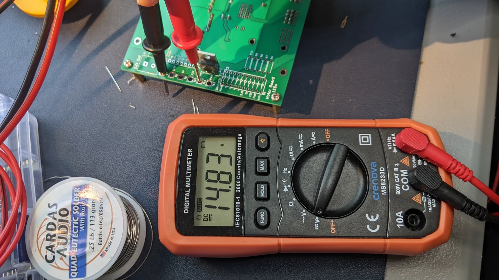 Photo creditelectrical/pcb/images/assembly/PXL_20230424_003626769.jpg JPL / California Institute of Technology and Open Source Rover contributors · Apache-2.0Resized without cropping and converted to WebP. |
|---|
| Figure 3.31: testing the Batt+ bus (positive lead from the battery) |
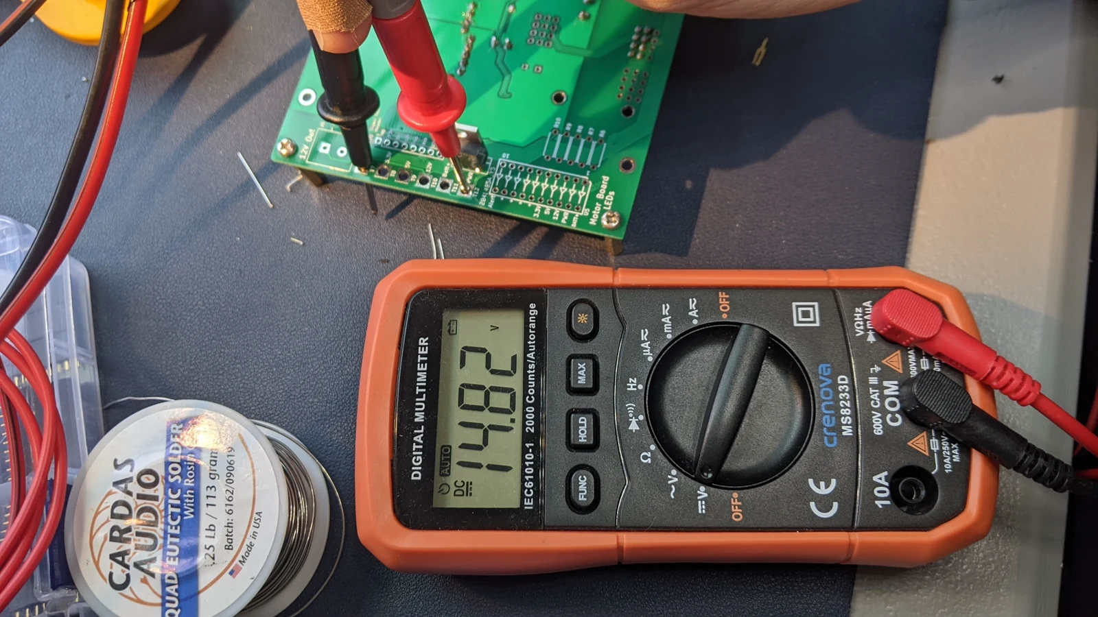 Photo creditelectrical/pcb/images/assembly/PXL_20230424_003630014.jpg JPL / California Institute of Technology and Open Source Rover contributors · Apache-2.0Resized without cropping and converted to WebP. |
|---|
| Figure 3.32: testing the PWR bus (main board power plane, after battery protection circuitry ) |
3.11 Install PCA9685 daughter board in U2 footprint and capacitor C3
:exclamation: Before continuing, make sure to disconnect the power supply from the previous step! You should not have the board powered on while installing components. :exclamation:
The PCA9685 is a PWM signal source, which we use as our corner motor controller.
First you will need to install female headers on the motor board, for the PCA9685 daughter board to mate with. You'll need:
- 6x1 female header
- 3x 2x4 female headers
You may use larger headers to fill all the holes in the U2 footprint, but it's not really necessary for the normal working configuration of the motor board. Attach these headers to the appropriate spots in the U2 footprint, as shown in Figure 3.33.
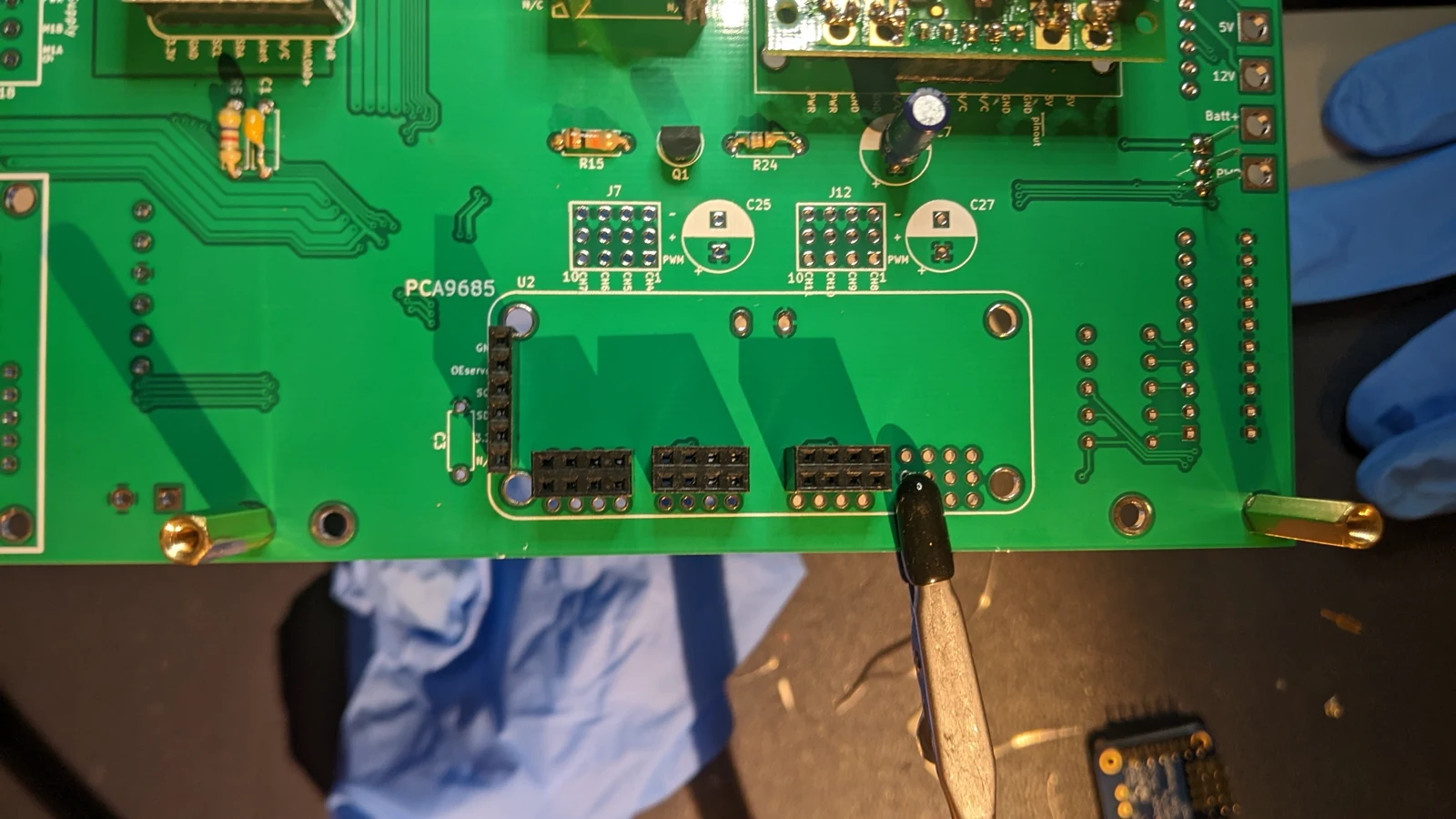 Photo creditelectrical/pcb/images/assembly/PXL_20230418_053133239.jpg JPL / California Institute of Technology and Open Source Rover contributors · Apache-2.0Resized without cropping and converted to WebP. |
|---|
| Figure 3.33: U2 with female headers installed |
You will need to attach male headers to the PCA9685 daughter board, as shown in Figure 3.34.
Also, 5v power is provided to the PCA9685 through the two holes at the top of the U2 header. You have a couple options for this.
Option 1 - Wires To connect these, I soldered 2 small wire leads on the PCA9685 daughter board, and then soldered them on to the motor board once I installed the PCA9685.
Option 2 - 1x1 Pins/Headers The V+ and GND on the PCA9685 don't exactly line up with the GND_motor and +5V_motor pins on the Motor board, but are close enough you can make them connect with two 1x1 pins on the PCA9685 and two 1x1 headers on the Motor board, as shown in Figure 3.35.
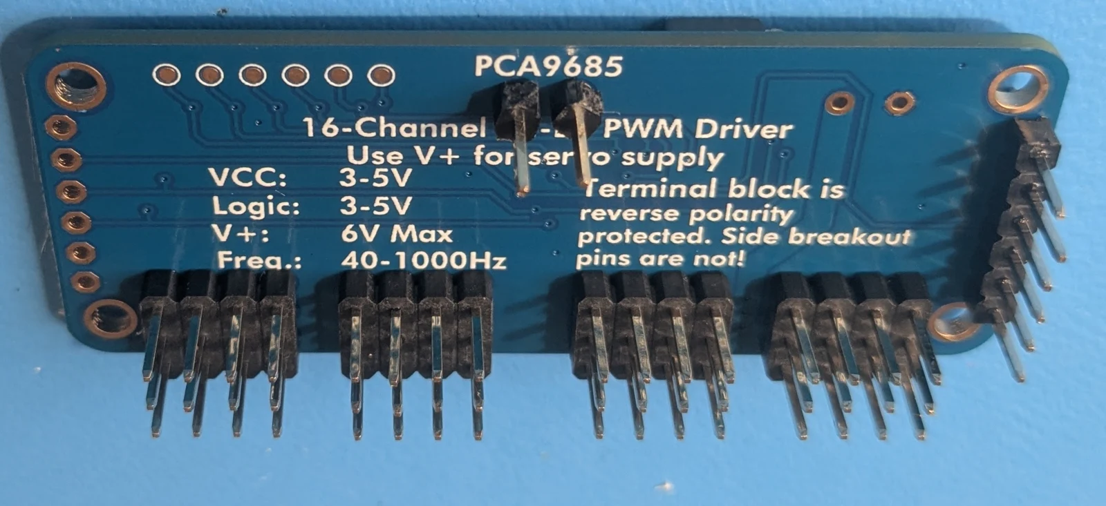 Photo creditelectrical/pcb/images/assembly/pca9685_headers.jpg JPL / California Institute of Technology and Open Source Rover contributors · Apache-2.0Resized without cropping and converted to WebP. |
|---|
| Figure 3.34: Male headers soldered onto PCA9685 daughter board |
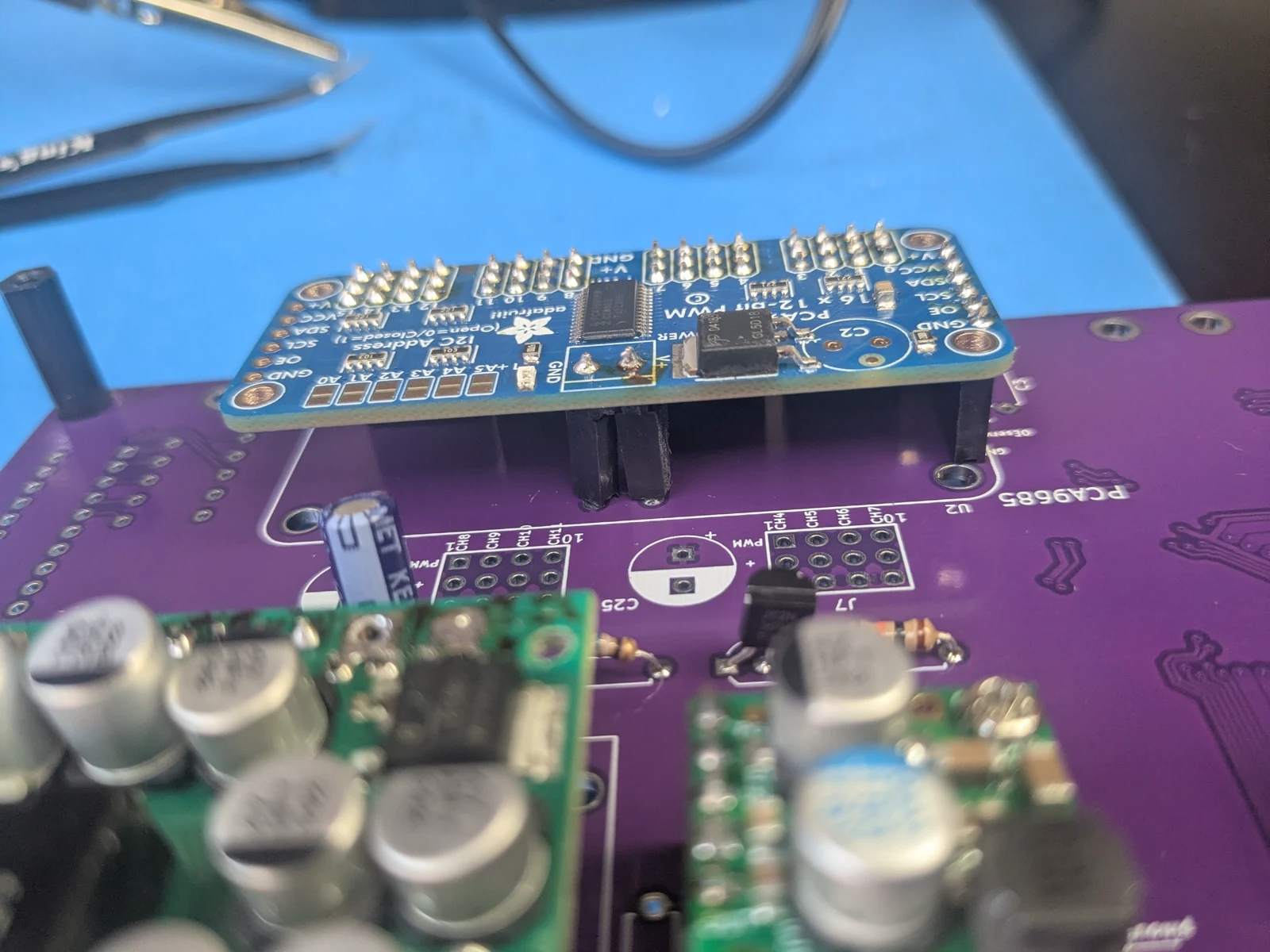 Photo creditelectrical/pcb/images/assembly/pca9685_installed.jpg JPL / California Institute of Technology and Open Source Rover contributors · Apache-2.0Resized without cropping and converted to WebP. |
|---|
| Figure 3.35: PCA9685 installed in motor board |
Finally install capicator C3 as shown in Figure 3.36.
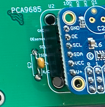 Photo creditelectrical/pcb/images/assembly/c3_installed.png JPL / California Institute of Technology and Open Source Rover contributors · Apache-2.0Unmodified source image. |
|---|
| Figure 3.36: C3 installed |
3.12 Install resistor R5 and capacitor C1
These are aids for the INA260, and can be left out if the IN260 is not used
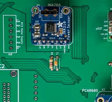 Photo creditelectrical/pcb/images/assembly/r5_c1.png JPL / California Institute of Technology and Open Source Rover contributors · Apache-2.0Unmodified source image. |
|---|
| Figure 3.37: PCA9685 installed in motor board |
3.13 Install J21, J20, and resistors R6,R7,R8,R9,R10
J21 is the interconnect header for the brain board, and J20 is a signal test header for the motor board
Use an 8x1 female header for J20.
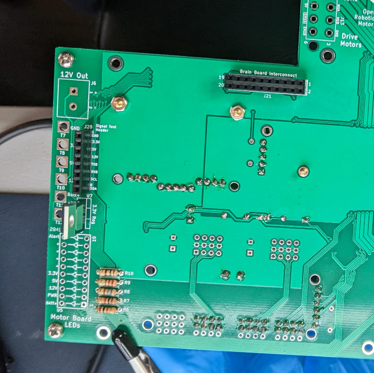 Photo creditelectrical/pcb/images/assembly/j20_j21_r6_r10.png JPL / California Institute of Technology and Open Source Rover contributors · Apache-2.0Unmodified source image. |
|---|
| Figure 3.38: Components installed, as viewed from top of board |
3.14 Test INA260 installation
To test the INA260, you will follow https://learn.adafruit.com/adafruit-ina260-current-voltage-power-sensor-breakout/arduino, and connect an Arduino to GND, SCL, and SDA on J20. You'll change the initalization step to
if (!ina260.begin(0x45)) {
to account for the I2C bus address. When you turn your power on, you should see something like this in the Arduino serial terminal:
Found INA260 chip
Current: 85.00 mA
Bus Voltage: 14456.25 mV
Power: 1230.00 mW
3.15 Install resistors R2,R3,R4
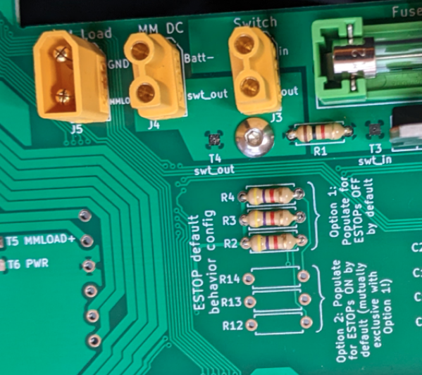 Photo creditelectrical/pcb/images/assembly/r2_r3_r4.png JPL / California Institute of Technology and Open Source Rover contributors · Apache-2.0Unmodified source image. |
|---|
| Figure 3.39: Components installed, as viewed from top of board |
3.16 Install Roboclaw standoffs, headers, and capacitors
Now we'll add the parts for roboclaw footprints RC1, RC2, and RC3.
First, install M2.5 x 15mm standoffs for the 3 RC footprints, as shown in Figure 3.40 and 3.41.
Next, solder in the two female headers for each RC footprint. You'll need a 2x10 and a 5x1 for each RC. These should be soldered into the holes on the side of each RC footprint.
Finally, install the following capacitors for each RC footprint:
- RC1: capacitors C13,C15,C17,C20 (Figure 3.41). Install on the top side of the board.
- RC2: capacitors C2,C4,C9,C10 (Figure 3.40). Install on the underside of the board.
- RC3: capacitors C14,C16,C18,C21 (Figure 3.41). Install on the top side of the board.
Technically, you can install the capacitors on either side of the board, but it makes for a cleaner presentation if you install them where their respective "C" labels are on the board.
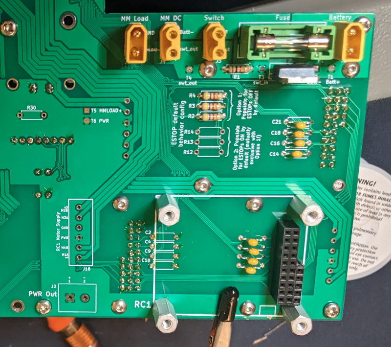 Photo creditelectrical/pcb/images/assembly/rc1_pop.png JPL / California Institute of Technology and Open Source Rover contributors · Apache-2.0Unmodified source image. |
|---|
| Figure 3.40: C2,C4,C9,C10 installed |
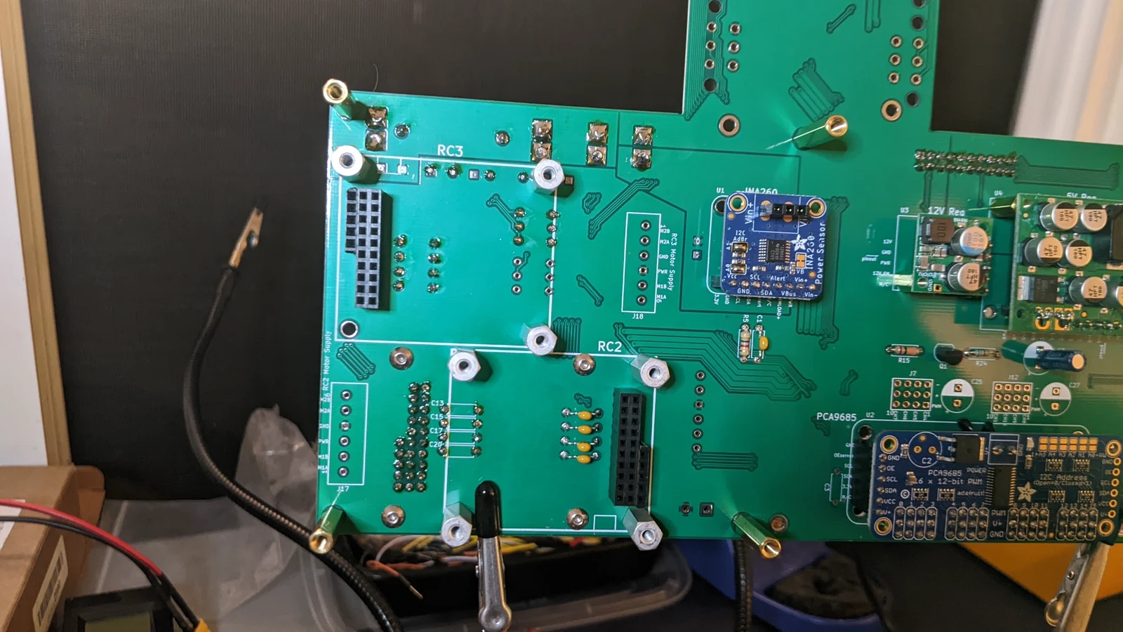 Photo creditelectrical/pcb/images/assembly/PXL_20230425_054908018.jpg JPL / California Institute of Technology and Open Source Rover contributors · Apache-2.0Resized without cropping and converted to WebP. |
|---|
| Figure 3.41: C13,C15,C17,C20 and C14,C16,C18,C21 installed |
3.17 Install motor supply headers J16,J17,J18
Figure 3.42 shows how these should be installed. J16 on the top of the board is installed in the same way.
Make sure to orient the connector in the proper direction, as indicated in the images.
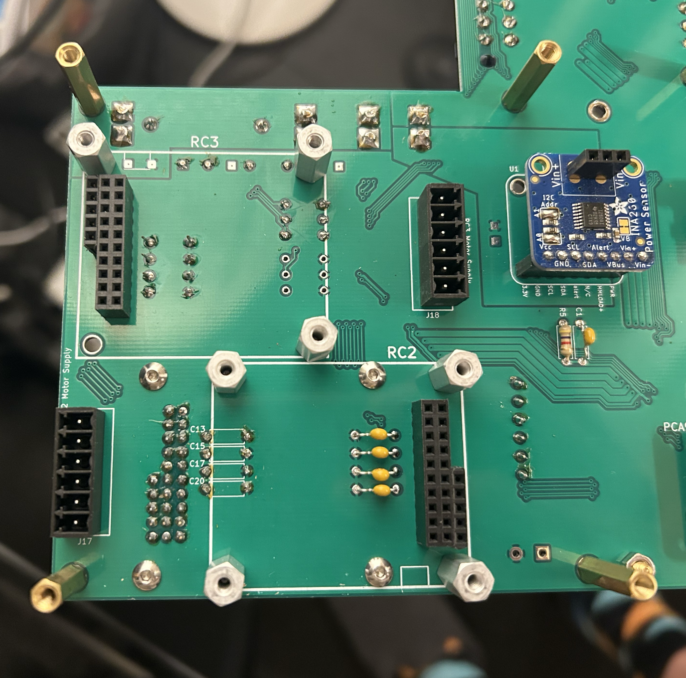 Photo creditelectrical/pcb/images/assembly/motor_supply_headers.png JPL / California Institute of Technology and Open Source Rover contributors · Apache-2.0Unmodified source image. |
|---|
| Figure 3.42: J17 and J18 installed, on bottom of board |
3.18 Install 3x Roboclaw boards in footprints RC1, RC2, RC3
First, wire the 6pos terminal block headers to the roboclaw boards, as indicated in Figure 3.43. Cut the wires to about 5cm and tin the ends.
Unless you have an older version of the PCB (v2.0.2 or earlier), wire the pins in the J16,J17,J18 headers directly to the pins on the corresponding side of the roboclaw - it is a direct 1-to-1 mapping all the way down, with no wires crossed. Use 16AWG wire (18AWG would also be fine)
Do this for all three roboclaws.
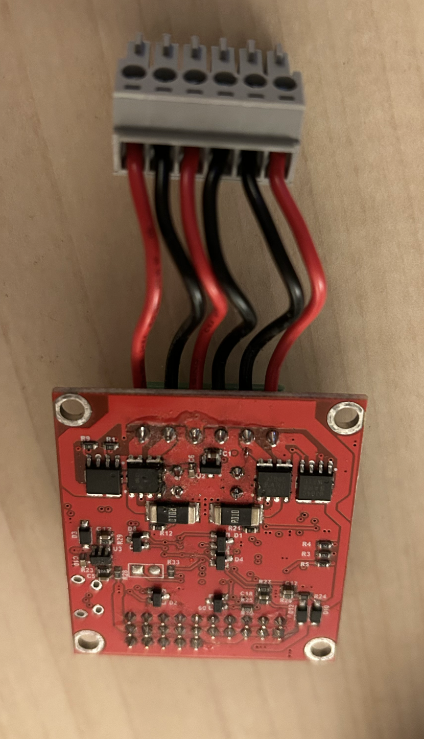 Photo creditelectrical/pcb/images/assembly/roboclaw_wired_1.png JPL / California Institute of Technology and Open Source Rover contributors · Apache-2.0Unmodified source image. 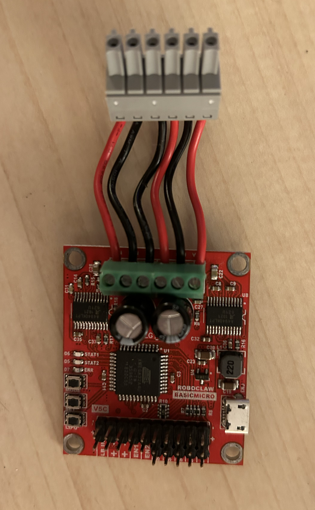 Photo creditelectrical/pcb/images/assembly/roboclaw_wired_2.png JPL / California Institute of Technology and Open Source Rover contributors · Apache-2.0Unmodified source image. |
|---|
| Figure 3.43: Wiring up the roboclaws |
Then install the 3 roboclaws in the RC1, RC2, and RC3 footprints. It doesn't matter which roboclaw goes in which footprint - we will later set unique addresses in software for each of them to communicate over the serial bus.
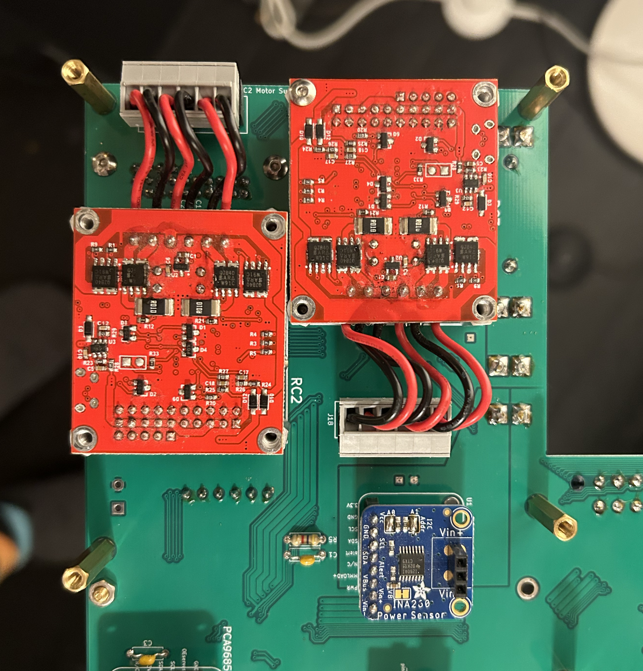 Photo creditelectrical/pcb/images/assembly/roboclaws_installed.png JPL / California Institute of Technology and Open Source Rover contributors · Apache-2.0Unmodified source image. |
|---|
| Figure 3.44: Installing the roboclaw boards |
3.19 Install capacitors C5,C6
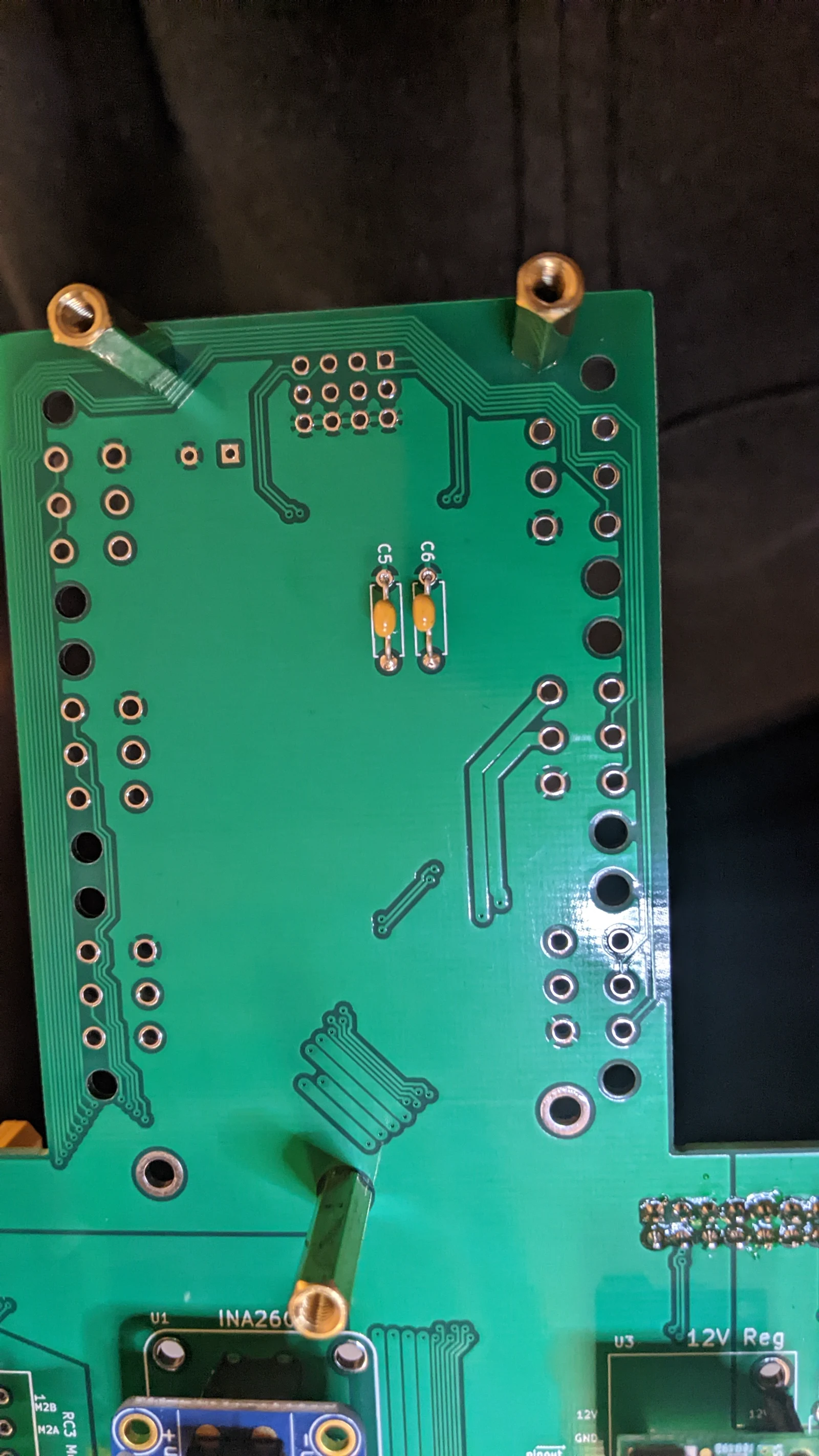 Photo creditelectrical/pcb/images/assembly/PXL_20230426_055549256.MP.jpg JPL / California Institute of Technology and Open Source Rover contributors · Apache-2.0Resized without cropping and converted to WebP. |
|---|
| Figure 3.45: Installing capacitors C5, C6 |
3.20 Install corner servo header J19, and capacitor C19
Make sure to install C19 in the proper direction, as shown in Figure 3.46. One side of the capacitor has negative polarity indicators on it, that should be installed opposite the "+" sign on the footprint.
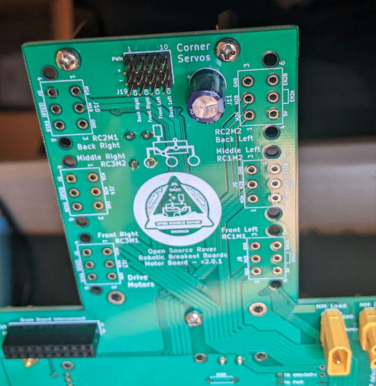 Photo creditelectrical/pcb/images/assembly/j19_c19.png JPL / California Institute of Technology and Open Source Rover contributors · Apache-2.0Unmodified source image. |
|---|
| Figure 3.46: J19 and C19 installed (top of photo) |
3.21 Install LED array U5
Make sure to align the slightly "chipped"/beveled corner of the LED array with the beveled corner of the U5 footprint, to have proper LED polarity
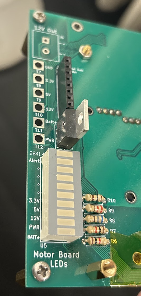 Photo creditelectrical/pcb/images/assembly/u5_installed.png JPL / California Institute of Technology and Open Source Rover contributors · Apache-2.0Unmodified source image. |
|---|
| Figure 3.47: LED array U5 installed |
3.22 Install drive motor headers J8,J9,J10,J11,J13,J14
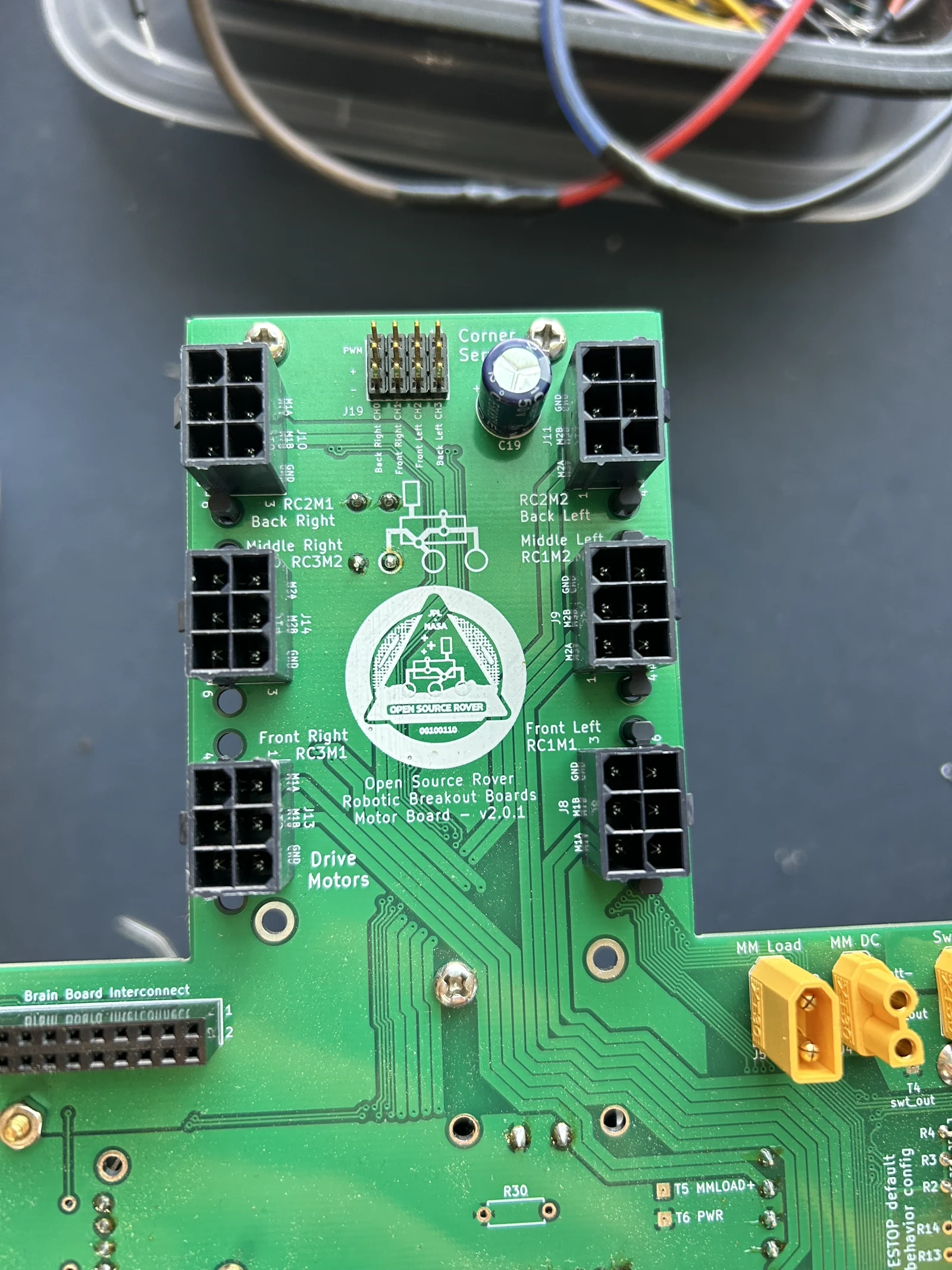 Photo creditelectrical/pcb/images/assembly/IMG_0827.jpeg JPL / California Institute of Technology and Open Source Rover contributors · Apache-2.0Resized without cropping and converted to WebP. |
|---|
| Figure 3.48: Drive motor headers installed |
4. Brain Board Assembly
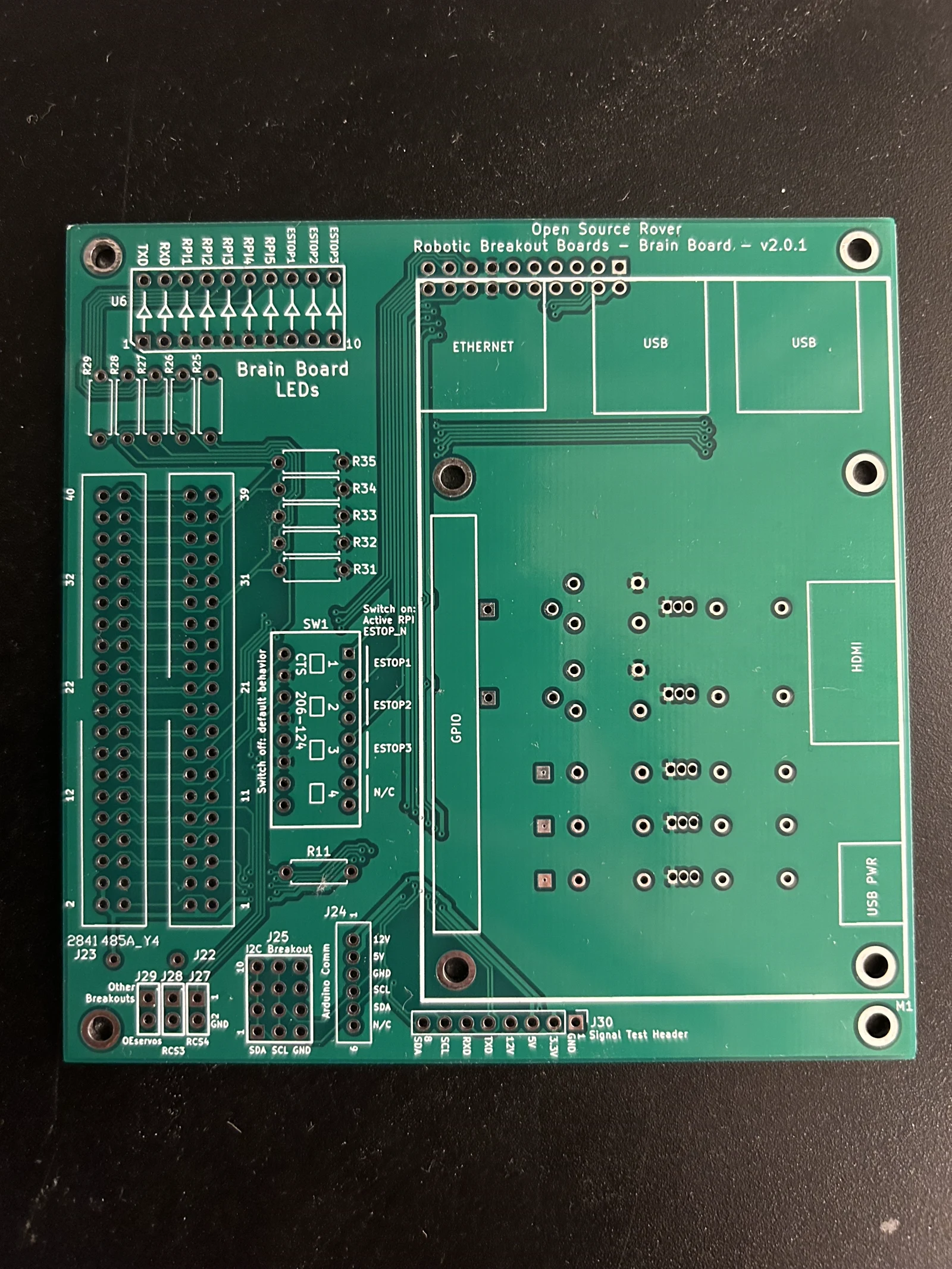 Photo creditelectrical/pcb/images/assembly/IMG_1491.jpeg JPL / California Institute of Technology and Open Source Rover contributors · Apache-2.0Resized without cropping and converted to WebP. 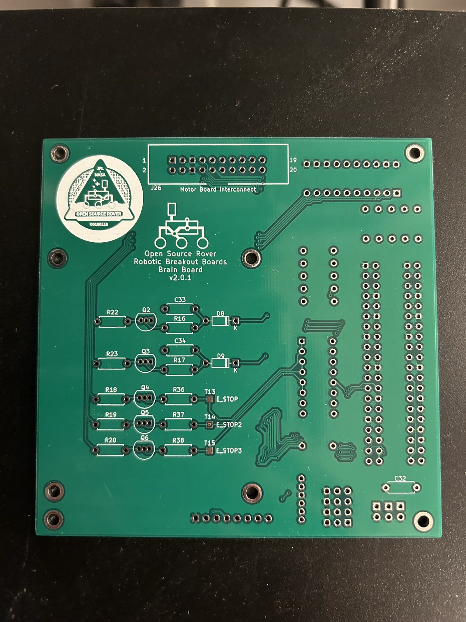 Photo creditelectrical/pcb/images/assembly/IMG_1492.jpeg JPL / California Institute of Technology and Open Source Rover contributors · Apache-2.0Resized without cropping and converted to WebP. |
|---|
| Figure 4.0: front (left) and back (right) of brain board |
4.1 Install resistors
Install 3 sets of resistors:
- R11
- R25,R26,R27,R28,R29
- R31,R32,R33,R34,R35
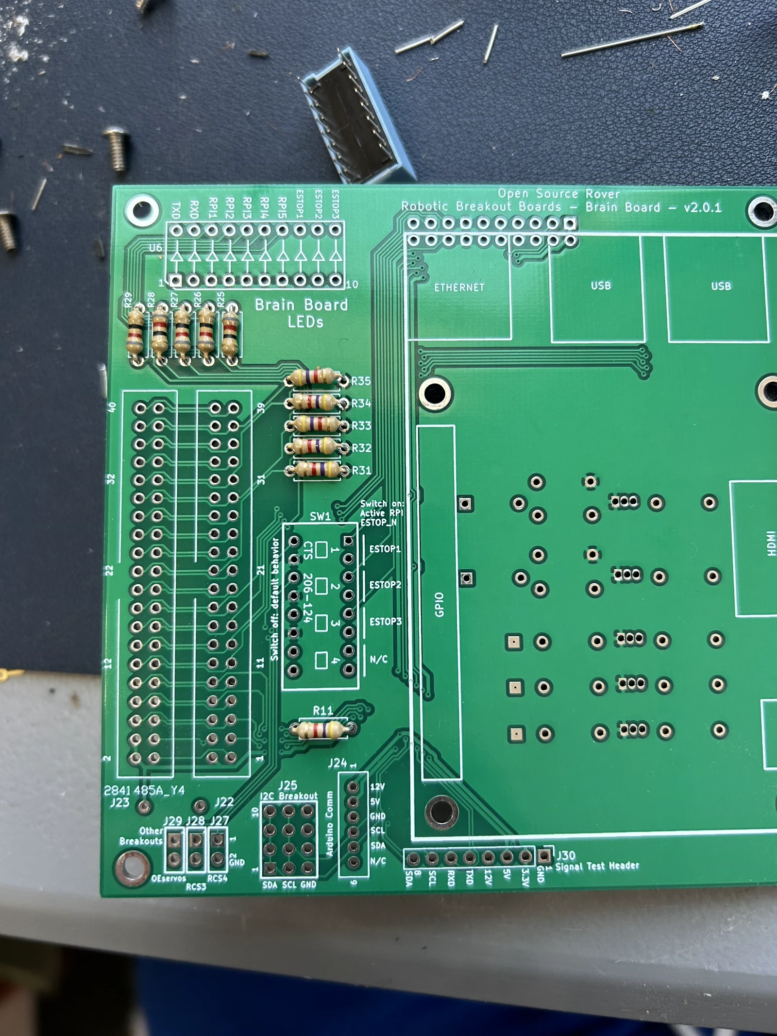 Photo creditelectrical/pcb/images/assembly/IMG_0834.jpeg JPL / California Institute of Technology and Open Source Rover contributors · Apache-2.0Resized without cropping and converted to WebP. |
|---|
| Figure 4.1: Resistors installed |
4.2 Install switch SW1
Make sure to install the switch in the correct direction to match the footprint.
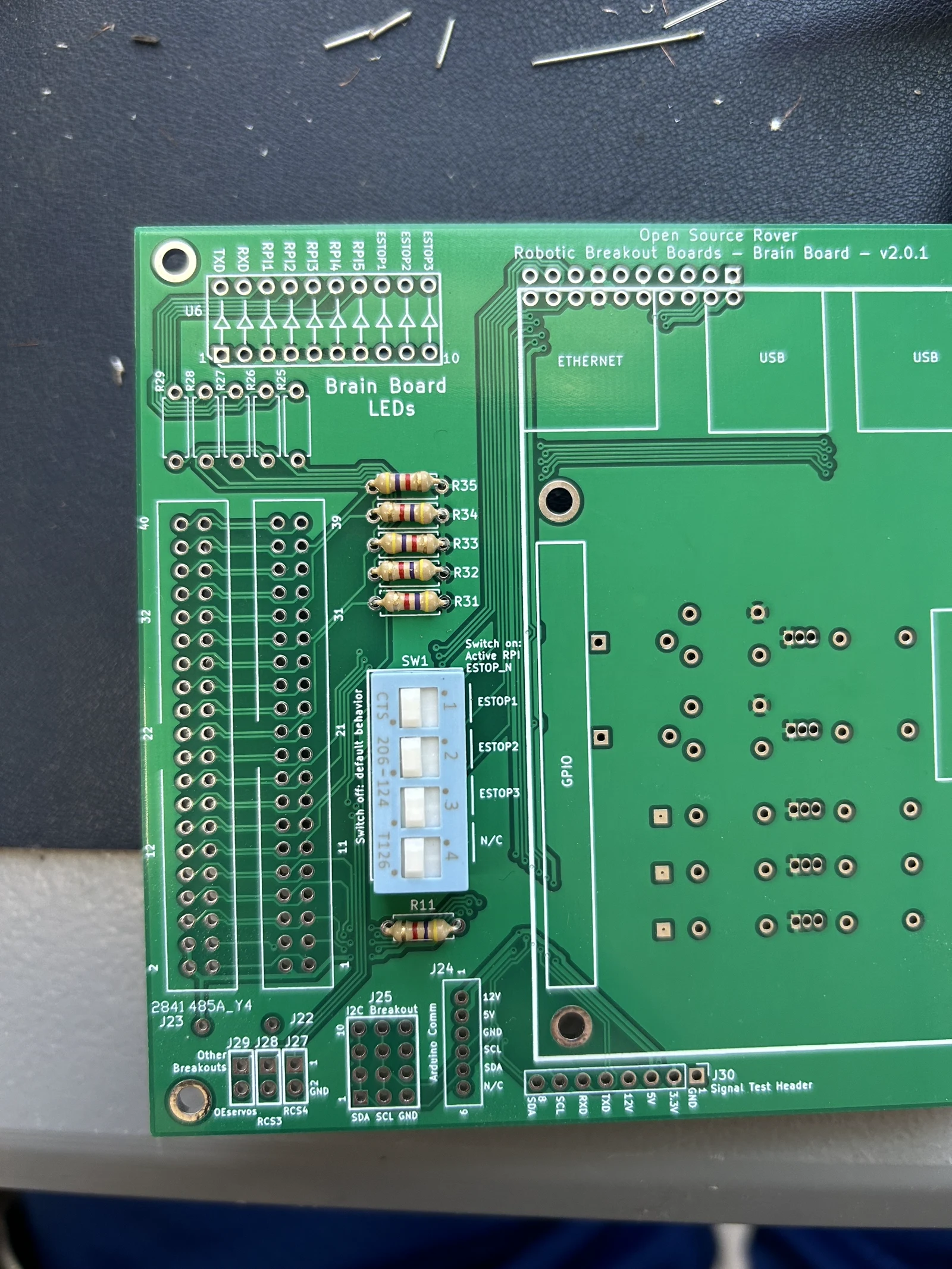 Photo creditelectrical/pcb/images/assembly/IMG_0832.jpeg JPL / California Institute of Technology and Open Source Rover contributors · Apache-2.0Resized without cropping and converted to WebP. |
|---|
| Figure 4.2: Switch SW1 installed |
4.3 Install LED array U6 and various headers on top of board
Install these components:
- U6 LED array
- J22,J23 raspberry pi ribbon cable headers
- J25 3x4 male headers - "i2c breakout"
- J24 1x6 shrouded male header (white color) - "arduino comm"
- J30 8x1 male header - "signal test header"
Make sure to align the slightly "chipped"/beveled corner of the LED array with the beveled corner of the U6 footprint, to have proper LED polarity
Make sure to match the gaps on the sides of the J22 and J23 headers with the gaps indicated in the silk screen for these footprints.
Make sure to install J24 with the gap facing to the right of the top side of the board (as shown in Figure 4.3)
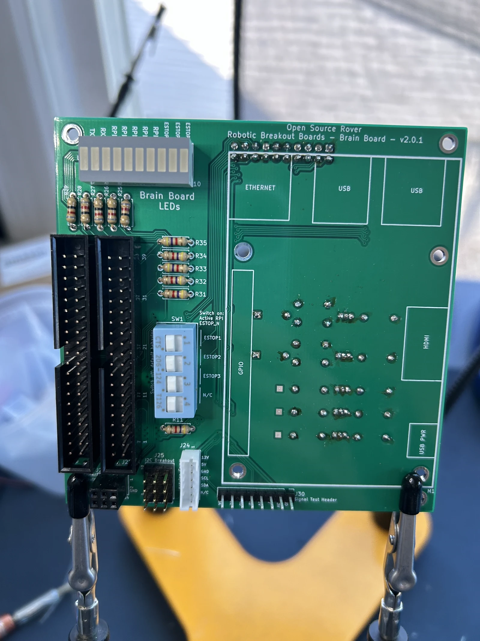 Photo creditelectrical/pcb/images/assembly/IMG_0842.jpeg JPL / California Institute of Technology and Open Source Rover contributors · Apache-2.0Resized without cropping and converted to WebP. |
|---|
| Figure 4.3: U6 and other headers installed |
4.4 Install J26 header and capacitor C32 on back of board
Make sure to match the gaps on the side of the J26 header with the gap indicated in the silk screen for the footprint
Ignore the resistors and Figure 4.4 for the moment
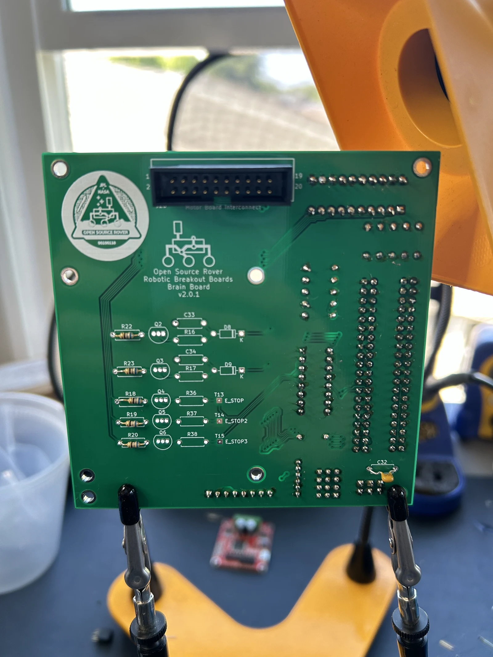 Photo creditelectrical/pcb/images/assembly/IMG_0839.jpeg JPL / California Institute of Technology and Open Source Rover contributors · Apache-2.0Resized without cropping and converted to WebP. |
|---|
| Figure 4.4: J26 (top) and C32 installed on back side of board |
Trim the leads of C32 before you continue.
Install other breakouts on top of board
Finally, install J27,J28,J29 2x1 female headers in front of the leads of C32
4.5 Install ESTOP and Serial TXD/RXD LED logic circuit components
Here we install all the components used for the E_STOP, E_STOP2, E_STOP3 logic signals and LED indicators, and also the LED indicators for serial TXD/RXD activity.
Install all of these as indicated in Figure 4.5:
- Q2, Q3, Q4, Q5, Q6 (BJT transistors) (Polarity Warning!)
- R18, R19, R20, R22, R23 (68 Ohms ±5% resistors)
- R16, R17, R36, R37, R38 (10k Ohms ±5% resistors)
- C33, C34 (10k pF ±10% 50V Ceramic Capacitors)
- D8, D9 (75V 300mA Diodes) (Polarity Warning!)
- Note: T13, T14, T15 should be left empty for probing.
Note that polarity/installation direction matters for both the BJTs and the diodes (D8,D9). Make sure to match these with the image correctly! (note the black band on one side of the diodes faces to the right in Figure 4.5)
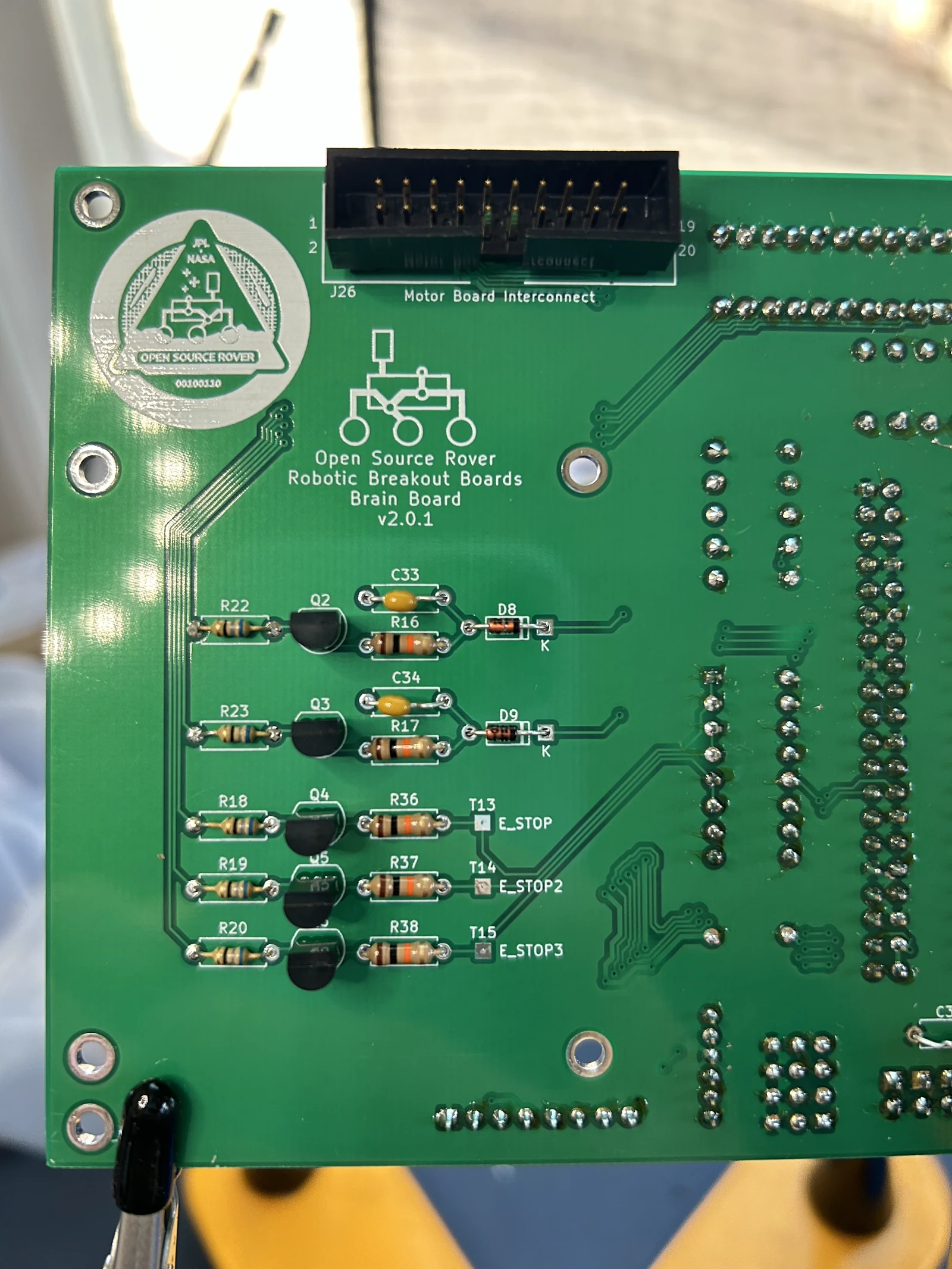 Photo creditelectrical/pcb/images/assembly/IMG_0841.jpeg JPL / California Institute of Technology and Open Source Rover contributors · Apache-2.0Resized without cropping and converted to WebP. |
|---|
| Figure 4.5: ESTOP and Serial TXD/RXD LED logic components installed |
4.6 Mount the Raspberry Pi board
Using M2.5 x 20mm standoffs, attach the raspberry pi to the top of the brain board, as shown in figure 4.6. Attach the ribbon cable from the GPIO on the Pi to J22.
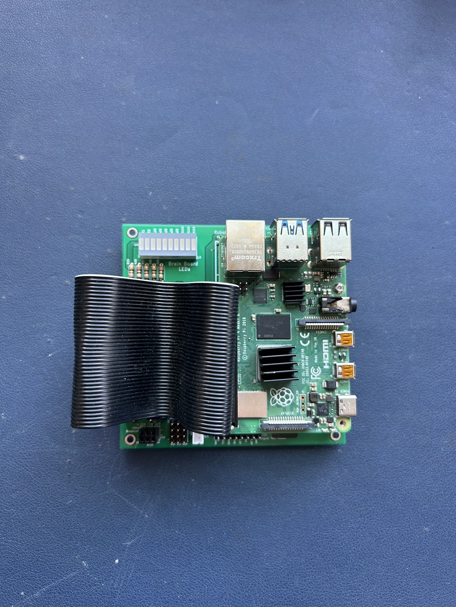 Photo creditelectrical/pcb/images/assembly/IMG_0844.jpeg JPL / California Institute of Technology and Open Source Rover contributors · Apache-2.0Resized without cropping and converted to WebP. 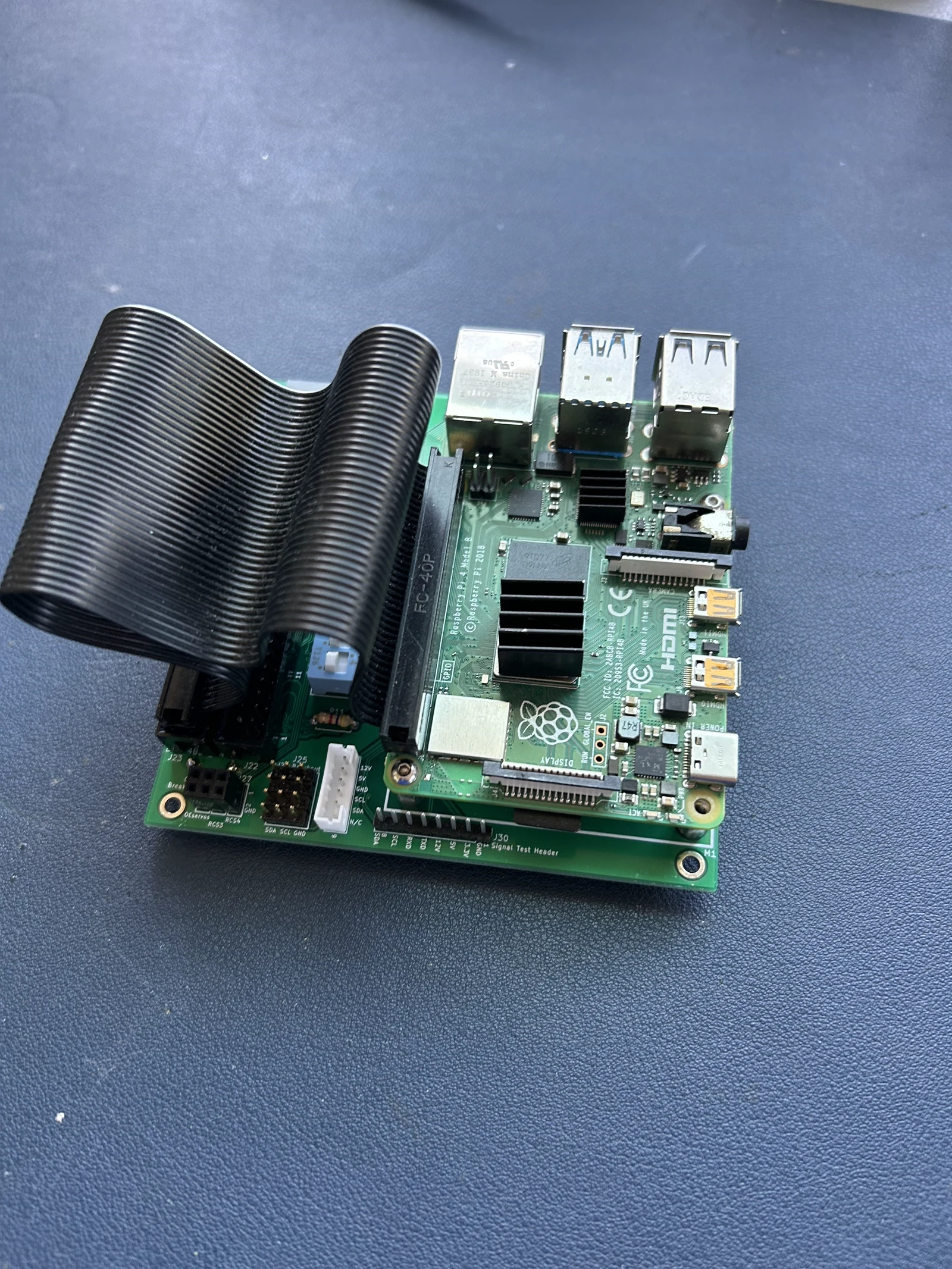 Photo creditelectrical/pcb/images/assembly/IMG_0845.jpeg JPL / California Institute of Technology and Open Source Rover contributors · Apache-2.0Resized without cropping and converted to WebP. |
|---|
| Figure 4.6: RPi mounted on the brain board |
Important Note if you are using a Raspberry Pi 5: The Raspberry Pi (RPi) 5 has different power requirements than previous RPi generations. The two 5v lines attached to the RPi via the ribbon cable are not to enough to adequately power the RPi 5, especially if attaching any peripherals, like a camera. Until further revisions are done to the PCB, it is recommeded to power the RPi 5 through a USB C connector. You can cut a USB C cable and identify the V+ and Ground lines using a digital multimeter, then solder those lines to the 5v and Gnd test connection points on the motorboard. You can then plug the USB C connector into the RPi 5 to power it. You can also order USB-C cables with PWR/GND broken out already (see Extra Parts List)
5. Motor Board and Brain Board Mating
Using M2.5 x 10mm standoffs, attach the brain board to the top of the motor board, as shown in Figure 4.7
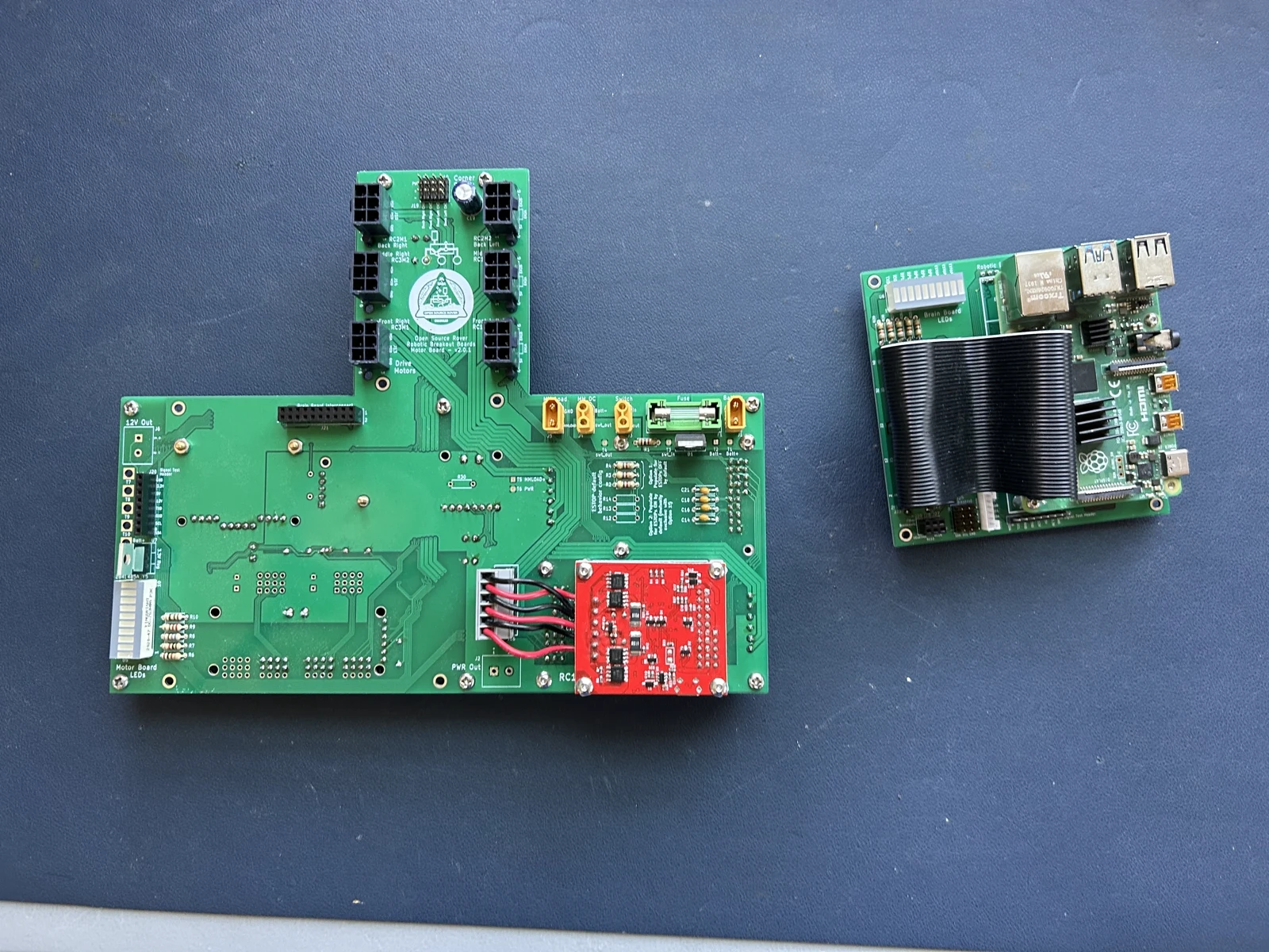 Photo creditelectrical/pcb/images/assembly/IMG_0847.jpeg JPL / California Institute of Technology and Open Source Rover contributors · Apache-2.0Resized without cropping and converted to WebP. Photo creditelectrical/pcb/images/assembled/complete_pcb_top.jpg JPL / California Institute of Technology and Open Source Rover contributors · Apache-2.0Resized without cropping and converted to WebP. |
|---|
| Figure 5.0: Mating the brain board to the motor board |
And now you're done with the assembly!
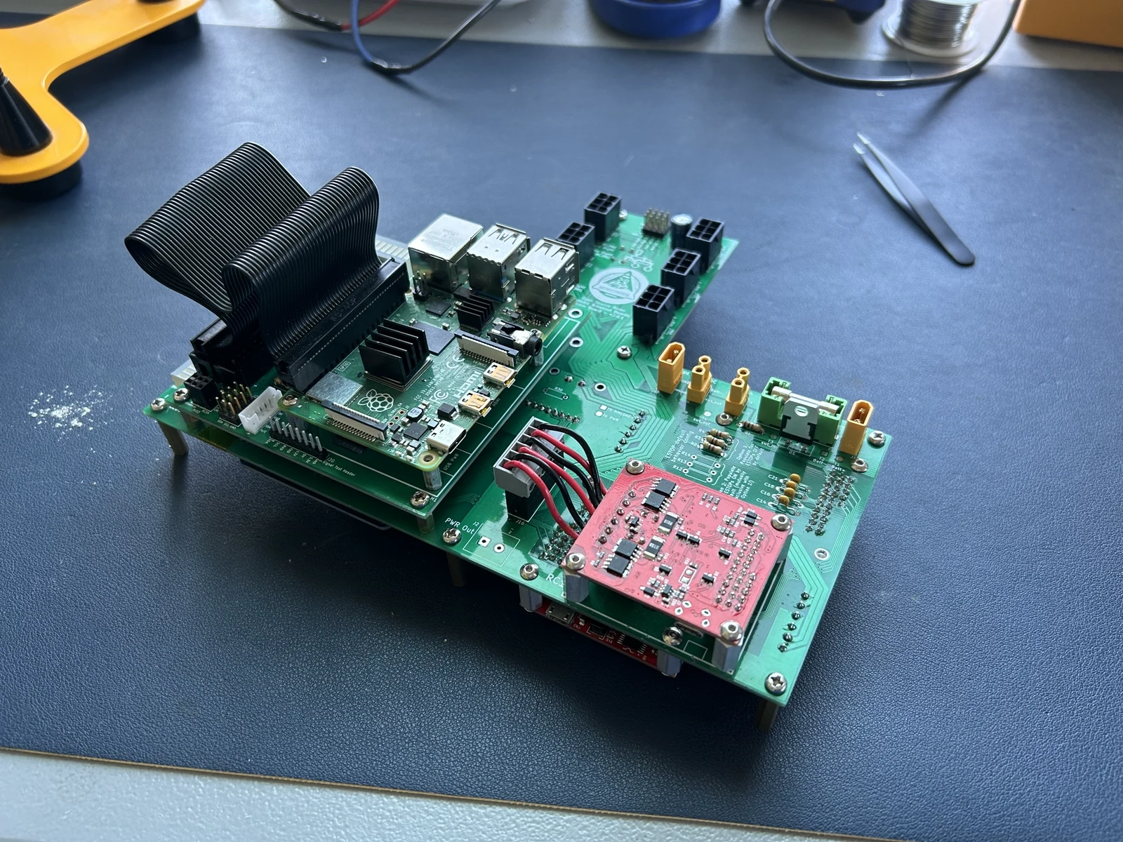
Photo credit
electrical/pcb/images/assembled/complete_pcb_top2.jpg
JPL / California Institute of Technology and Open Source Rover contributors · Apache-2.0Resized without cropping and converted to WebP.
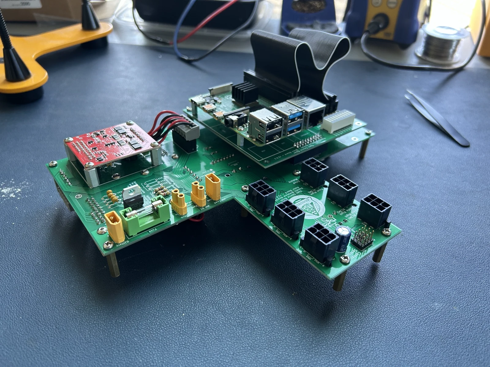
Photo credit
electrical/pcb/images/assembled/complete_pcb_top3.jpeg
JPL / California Institute of Technology and Open Source Rover contributors · Apache-2.0Resized without cropping and converted to WebP.
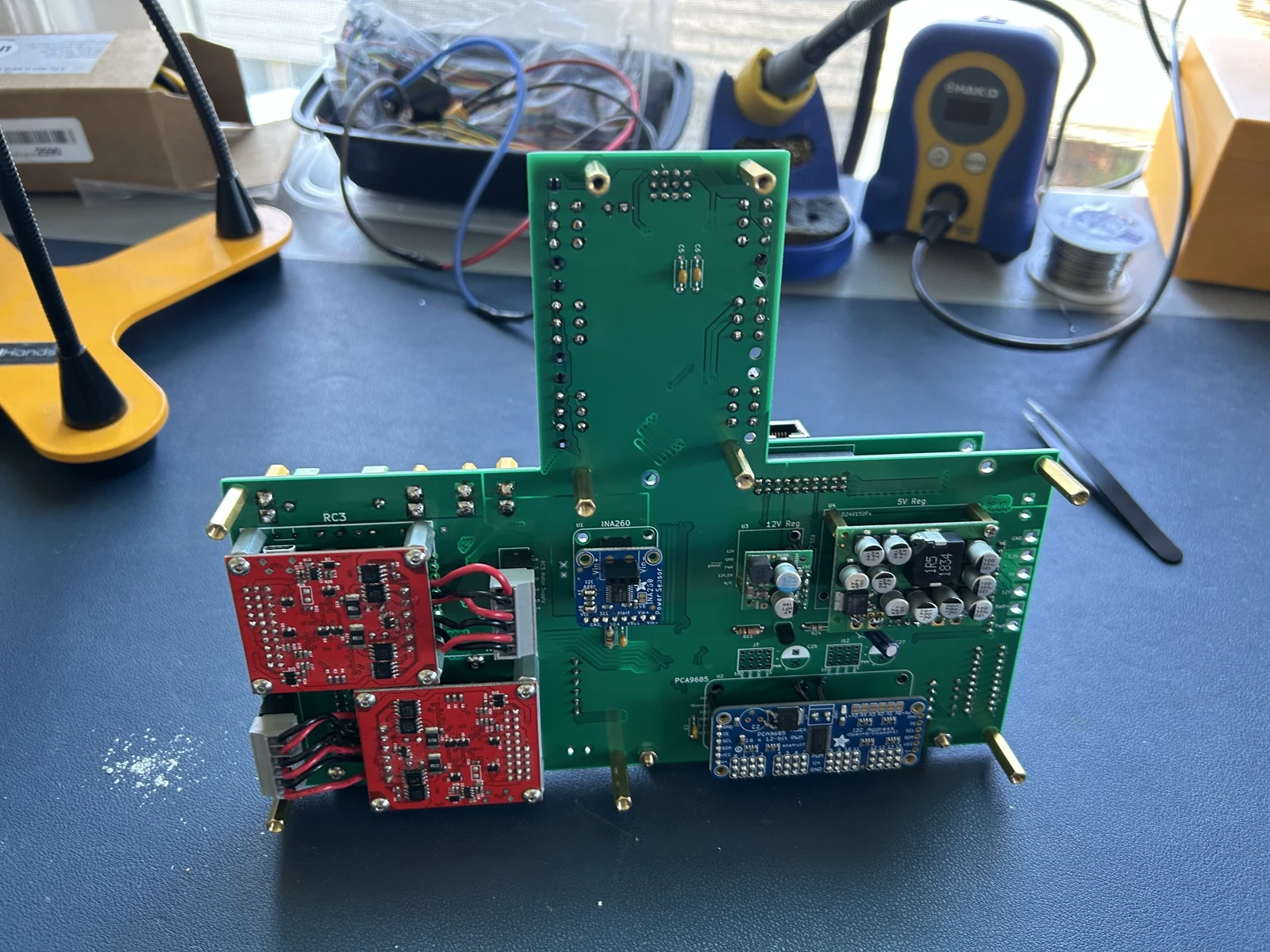 Photo creditelectrical/pcb/images/assembled/complete_pcb_bottom_with_ina260.jpeg JPL / California Institute of Technology and Open Source Rover contributors · Apache-2.0Resized without cropping and converted to WebP. |
|---|
| Figure 4.8: Completed control board (with INA260) |
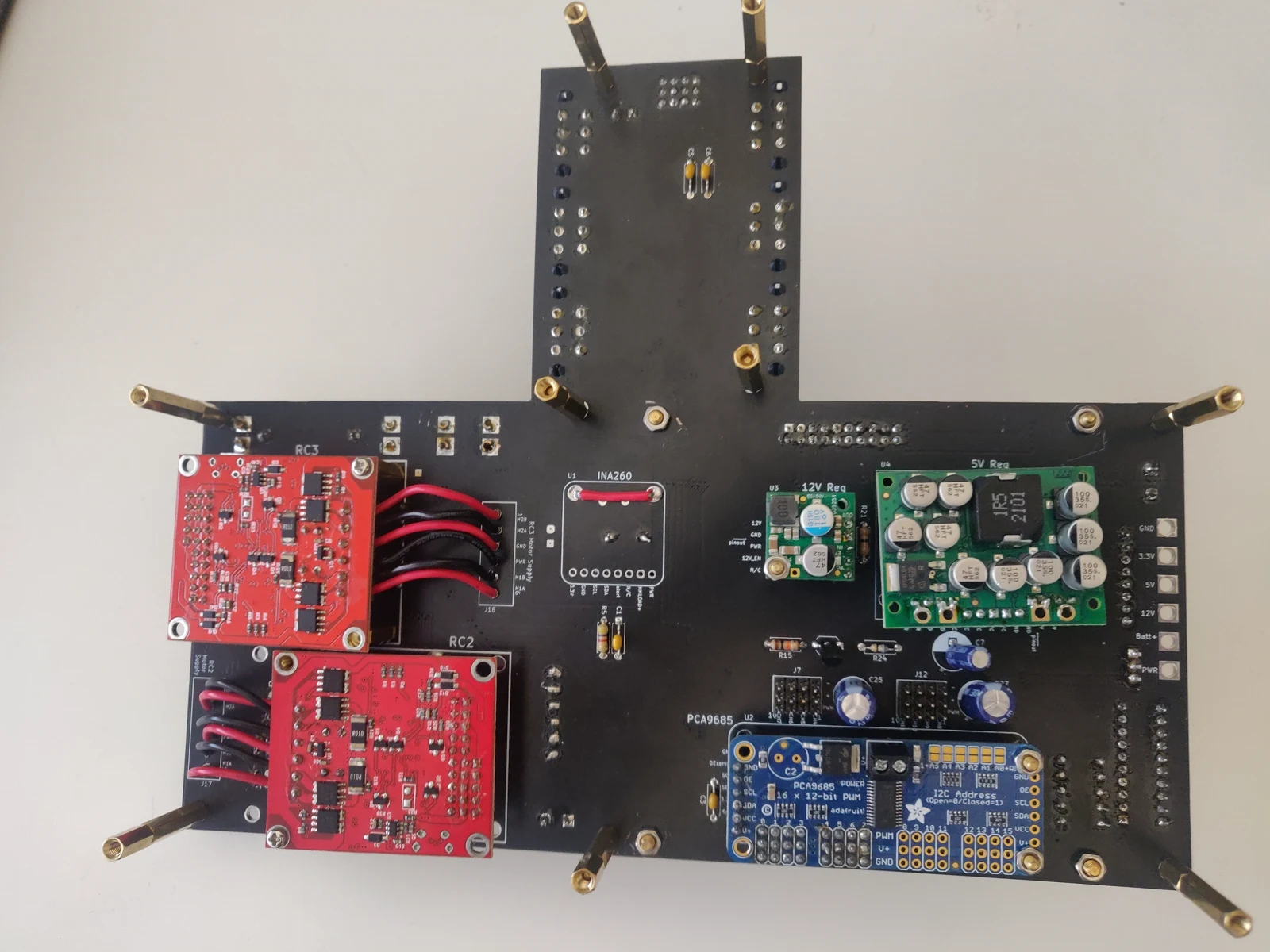 Photo creditelectrical/pcb/images/assembled/complete_pcb_bottom_no_ina260.jpg JPL / California Institute of Technology and Open Source Rover contributors · Apache-2.0Resized without cropping and converted to WebP. |
|---|
| Figure 4.9: Completed control board (INA260 bypassed) |
Finally, we'll move on to testing and configuration.
6. Testing the PCB and wiring for the drive motors
Before we insert the wiring and PCBs into the mechanical assemblies, we'll test and configure the drive motors, wiring, and PCB. This allows us to fix these critical parts if something doesn't look right and allows us to move to running the software as soon as the rover is assembled.
For this you will need:
- wiring you made earlier in wiring readme
- 6 drive motors
- completed PCBs
- a power source: a benchtop power supply or a charged battery
- wheel and bore hub
Secure the PCB assembly so it doesn't fall or move while it's on. You can attach it to the bottom body plate already. Avoid contact with any surfaces that can generate high-voltage sparks like carpets as that can destroy the electrical components.
Arrange the drive motors around the PCB and connect them using the wiring. Since we'll be calibrating them, make sure you connect the right motors to the right PCB receptacles. It helps to mark them using a sticky note or marker. The silk screen lettering should help here.
Connect a power source to your board as you did before. Verify that the roboclaws all receive power. A green light should be on on each roboclaw.
6.1 RoboClaw Testing and Verification
In this section you will be going one by one and and testing the operation of the RoboClaw Motor controllers. You will be doing this by using the GUI provided by the manufacturer of the motor controllers. The GUI can be found at the BasicMicro website, under general downloads, then BasicMicro Motion Studio.
You'll also need the USB RoboClaw Windows Driver from the RoboClaw General Downloads section of the page. This should be installed before you run the Motion Studio.
To use the GUI, insert a USB to Micro USB cable from your computer to the motor controller you are going to be testing. In the Basic Motion GUI you should see an available device appear. It might require an update to proceed. Install the latest firmware update and then connect to the device.
Verify that all status lights are green and that the following values are shown at the top:
Temperature1: ~30 M1/M2 Amps: 0.00 M1/M2 Encoder: 0 M1/M2 Speed: 0 Main Battery: Between 11.5-16.7V Logic Battery: 5V Model: 2x7a
6.2 Configuring general settings
The addresses for each Roboclaw unit by default are 128 which we want to change such that the Raspberry Pi can distinguish between Roboclaws and thus motors. We'll leave Roboclaw 1 at 128 and set Roboclaw 2 and 3 to 129 and 130 respectively.
In the General Settings tab:
- under
Setup, setControl ModetoPacket Serial - Enable the
Multi-Unitmode flag - Under
Serial, set thePacket Serial Addressto either 128, 129, or 130 depending on which roboclaw is plugged in - set the
Baudrateto115200 - Under
I/O, make sureEncoder 1 ModeandEncoder 2 Modeare both set toQuadrature - Under
Battery, setMax Main Batteryto18.5VandMin Main Batteryto11.5V
Next, we'll check the correct direction and calibrate velocity before we repeat the process for the other roboclaws and motors.
6.3 Prepare PWM signal
Click on the PWM tab. We will now send a PWM signal to the motor and test that connections are all made correctly to the motor and encoder. Start by selecting the Enable Space Bar Stop All button in the bottom left which allows you to set velocity to zero when you hit the space bar.
6.4 Vary PWM signal
Slowly move the slider bar for the corresponding motor output channel. Verify that the right motor is spinning and that the encoder value is also changing.
- If there is no movement, the motors aren't getting current through the MA and MB wires. Check your wiring and look for red status lights within the Motion Studio GUI to troubleshoot.
- If the motor spins but the encoder value for that same motor/channel (M1 or M2) isn't changing, there likely is an issue with your encoder cabling. Use a multi-meter to verify connectivity.
- If all your connections are correct, you may have to test your solder contact between the components on the board itself.
Note: When troubleshooting electrical connections, always remove power to the PCB to prevent shorting and injury. Switch direction of the slide bar and verify that it spins the other direction and the encoder value does the opposite of previous as well.
Once you've verified this, we'll focus on the direction. We want the motor to spin as in the diagram below when we send a positive PWM:
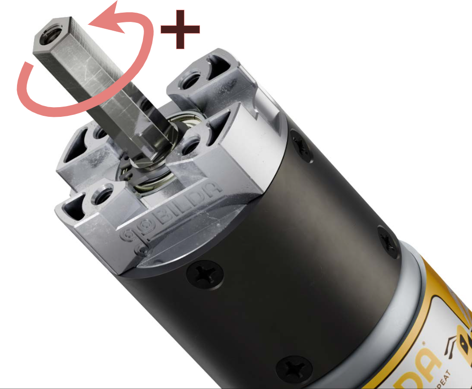
Photo credit
electrical/pcb/images/motor_direction_diagram.png
JPL / California Institute of Technology and Open Source Rover contributors · Apache-2.0Unmodified source image.
For both motors check that the direction matches the diagram. If it doesn't, for that motor in the General Settings tab, select M1 Reverse. Check again to verify it matches. Now verify that the encoder value increases when you send a positive PWM for each motor. If it doesn't, select the invert checkbox in General Settings and verify again.
6.5 Calibrate Velocity Settings
Click on the Velocity Settings tab. Here we will tune the velocity settings of the motor; these can only be done after setting the PWM direction in the previous step so ensure that those are done first. Furthermore, to get a precise calibration the wheels should be attached to the motors as they add some inertia to the system. Reference the wheel assembly instructions to see how to attach the wheels to the motor.
While the individual parameters can be tuned to precise values, for an initial/minimum setup we can use the Autotune feature. To do this first make sure your motor and wheel can freely spin (i.e. elevated off the ground and not in contact with anything). Then, select Tune M1 under Autotune. The motor will rock back and forth several times slowly and quickly. Once the motor stops, the tuning is complete. Do the same for the second motor by selecting Tune M2. The velocity calibration is now complete.
The individual PID values can also be tuned manually after autotuning to tweak the motor performance. Roboclaw has an overview of all of the velocity settings here.
Important: Make sure to save these settings to each Roboclaw's non-volatile memory by clicking on the
Devicemenu >Write Settings. Repeat starting from Section 6.1 for the other two roboclaws.
Notes on the schematic (Control Board.sch)
- for library part ED2989-ND-USB, made VCC and GND passive because these are alternative ways to power the +5V bus, and the electrical rules check-in kicad doesn't allow multiple power output sources for the same bus. Normally this bus is powered by the battery and voltage regulators.
- have to use a PWR_FLAG on the +BATT bus because this power net is not output from the battery directly, it's only available after a series of passive components (diode, fuse)
- also, doesn't really make sense to mark the battery connector ground pin as a "power output", so use PWR_FLAG for GND bus as well
- the 3.3v bus is not actaully powered; RPi's get power on the 5v bus
- We need separate power buses on the two boards, thus we created different power port symbols (e.g. the little triangle that says "GND")
- the ports on the motor board are post-fixed "_motor"
- the ports on the brain board are post-fixed "_brain"
- We need different power ports because they function as a "global label" that can be seen across all sheets in a single schematic. So it's important to have different names.
- Note it's different for "net labels" - those are local in scope, to the given sheet
- see https://forum.kicad.info/t/understanding-power-port-components/8945/14 for more background
Important things to keep in mind when updating schematics
- make sure you're being cleanly about updating symbols in the schematic
- you should update them in the JPL_Robotics_Lib.lib file, then pull those changes into the local schematic file in kicad
- if kicad creates "cache" or "rescue" libarary files, think before committing those to git.
- cache files should be okay, but that's unclear. Ask someone before adding those to git versioning.
- rescue files should not be commited - but that's also unclear. Ask someone before adding those to git versioning.
- Reference Designators
- it's important to retain the same reference designators (e.g. J12, U1, C3, etc) when revving the PCB - a lot of the discussion in the open source rover forums have referenced components by the reference designator, so that's a useful well-known name.
- whenever annotating reference designators in kicad (with
Annotate Schematic...), make sure to checkkeep existing annotations - of course, if new components are added to the PCB schematic, these will need new completely designators. It's fine to use auto numbering for these.
- in the worst case, you can always go into the .sch file and fix things by hand in a text editor
Components
LM358
- Why do we use these?
- for buffering the raw encoder signals
- voltage follower layout
- datasheet
- see table 6-1 for pin functions
Roboclaw
- [Datasheet](https://downloads.basicmicro.com/docs/roboclaw_datasheet_2x30A.pdf](https://downloads.basicmicro.com/docs/roboclaw_datasheet_2x30A.pdf)
- see page 5 and 6
- Pins
- We don't use the encoder power (+/-, "PWR1/2" in the jpl robotics library) connections on the roboclaw pin header because we supply this via the screw terminals
Raspberry Pi
- Datasheet
- For EEPROM ID SD and SC
- See page 9 of the datasheet
- SD is i2c clock (so this pin is set to output)
- SD is i2c data (so this pin is set to bi-directional)
Voltage regulators
Inter-board connectors
- Male
- PEC10DAAN
- Digikey
- Summary drawing
- Female
- PPTC102LFBN-RC
- Digikey
- Summary drawing
Secondary E-stop (e_stop 2) header
- PPTC021LFBN-RC
- Digikey
- Summary drawing
Adafruit INA260 headers
- The ina260
- 8 pin header
- PEC08SAAN
- Digikey
- Summary drawing
- Don't need to connect vbus because we're doing high side sensing
- 2 pin header
- PEC02SAAN
- Digikey
- note! This header is actually 0.1" pitch, but we need 0.2" pitch. So the builder will have to go in and manually cut the pins apart. Shouldn't be too hard though.
- for this reason, using a custom footprint with 0.2" spacing
Adafruit 16-Channel Servo Driver
- 6 pin header
- PPTC061LFBN-RC
- Digikey
- Motor output headers
- PPTC041LFBN-RC
- Digikey
- 3 of them for each section of 4 output channels on the servo driver board
- note that we don't need to connect the two pin power header, because we aren't routing power through the servo controller board, we're exclusively providing it through the control board
Corner servo motor connectors
- 3 pin header
Regenerating the board documentation
Everything under documentation/ is generated from the KiCad board,
not captured by hand. The scripts live in documentation/utilities/ and resolve
their paths relative to themselves, so they can be run from anywhere; the
examples below assume you are in the project directory
(electrical/pcb/control_board/), one level above this file.
Requires KiCad 8 or newer for the kicad-cli subcommands used here. Verified
against KiCad 10.
| Script | Produces | Reads |
|---|---|---|
utilities/split_boards.py | gerbers/{brain,motor}_board.kicad_pcb | Control_Boards.kicad_pcb |
utilities/fit_svg_viewbox.py | re-fits an SVG canvas (called by export_layout.sh) | the exported SVGs |
utilities/render_3d.sh | documentation/3d_images/*.png | the split per-board files |
utilities/export_layout.sh | documentation/layout/*.svg | Control_Boards.kicad_pcb |
utilities/export_gerbers.sh | gerbers/gerber_files/ + zips | the split per-board files |
utilities/export_schematic.sh | documentation/schematics.pdf | Control_Boards.sch and its sub-sheets |
The two output scripts are independent — the layout export does not need the split, only the 3D render does.
3D board images
1. Split the combined board
Control_Boards.kicad_pcb holds both boards in a single design, so it
cannot be rendered per board. Produce single-board copies first:
python3 documentation/utilities/split_boards.py \
    Control_Boards.kicad_pcb --outdir gerbers --write
Run it without --write first to preview. It reports how many items land on
each board and lists the reference designators, so you can check the result
before anything is written — for v2.0.3 that is 52 footprints on the brain board
and 96 on the motor board.
The split is geometric: the two board outlines are separated by a 51 mm empty band in Y (the motor board spans y = -78..100, the brain board y = -229..-129), so a horizontal cut at y = -100 divides the design cleanly. The splitter also rewrites 3D model paths on the way out — see Model paths.
2. Render
documentation/utilities/render_3d.sh
This writes eight PNGs into documentation/3d_images/: brain_top,
brain_top_iso, brain_bottom, brain_bottom_iso, and the same four for
motor.
render_3d.sh does not run the splitter. If the per-board files are missing
it stops and prints the split_boards.py command from step 1. Nothing checks
whether they are stale, so re-run step 1 yourself whenever
Control_Boards.kicad_pcb changes — otherwise you will silently render the
previous revision's geometry.
Options
| Variable | Default | Notes |
|---|---|---|
VERSION | v2.0.3 | version label shown in the progress output; paths no longer depend on it |
QUALITY | basic | basic matches the flat look of the v2.0.1 images; high and ultra raytrace |
BACKGROUND | opaque | or transparent, checkered |
PRESET | FOLLOW_PLOT_SETTINGS | or FOLLOW_PCB, or a preset you defined in the 3D viewer |
KICAD_CLI | auto-detected | set this if kicad-cli is not on PATH or in the macOS app bundle |
VERSION=v2.0.4 QUALITY=ultra documentation/utilities/render_3d.sh
The isometric camera angles are the ISO_TOP and ISO_BOTTOM variables near
the top of the script. kicad-cli pcb render --side accepts only top and
bottom, so the three-quarter views come from --rotate 'X,Y,Z' instead;
negative values need quoting in zsh. -h is the short form of --height, so
use kicad-cli pcb render --help for the full option list.
Per-board canvas sizes are set in the canvas() function — the motor board is a
wide T, the brain board is square.
Layout SVGs
documentation/utilities/export_layout.sh
This writes documentation/layout/all_layers.svg plus one file per layer
under separate_layers/. It plots the combined board, which is what v2.0.1
was plotted from, so no split is needed and the output filenames keep the v2.0.1
spelling (Control_Boards-F_Cu.svg and so on) and stay directly comparable.
Six layers are plotted: F.Cu, B.Cu, F.Silkscreen, B.Silkscreen,
Edge.Cuts and Dwgs.User. v2.0.1 also plotted F/B.Adhes and F/B.Paste;
all four came out empty on this design — 4.7 KB of boilerplate each — so they
are omitted. To change the set, edit the LAYERS list at the top of the script;
each entry is <kicad layer name>:<output basename>.
Options
| Variable | Default | Notes |
|---|---|---|
VERSION | v2.0.3 | version label shown in the progress output; the output path no longer depends on it |
PAGE_SIZE_MODE | 2 | 0 drawing-sheet page size, 1 current page size, 2 board bounding box only |
DRAWING_SHEET | exclude | the board's paper is A4 while the board is 220 x 329 mm, so the sheet lands off the board area entirely |
FIT_VIEWBOX | 1 | re-fit each canvas to its content; 0 leaves KiCad's canvas alone |
MARGIN | 2 | mm of padding around the fitted content |
THEME | (board default) | try "KiCad Classic" to match the v2.0.1 colours |
KICAD_CLI | auto-detected | as above |
THEME="KiCad Classic" MARGIN=5 documentation/utilities/export_layout.sh
PAGE_SIZE_MODE=0 DRAWING_SHEET=include documentation/utilities/export_layout.sh
The same list is in the comment block at the top of utilities/export_layout.sh.
fit_svg_viewbox.py can also be run by hand on any KiCad-exported SVG —
documentation/utilities/fit_svg_viewbox.py FILE... [--margin MM] [--quiet]. It
rewrites files in place and is idempotent, so re-running it is harmless.
If a layer name is rejected, the script reports which one and keeps going with
the rest, then exits non-zero. Layer names changed between KiCad 5 and 6 —
F.SilkS became F.Silkscreen — so if you retarget this at an old board file,
that is the first thing to check.
Why the canvas is re-fitted
--page-size-mode 2 crops to the Edge.Cuts bounding box, 220 x 329 mm. Two
Dwgs.User annotations live outside that box and were being cut off:
| Note | Position | Relative to the board |
|---|---|---|
BRAIN BOARD caption | y = -230.39 | 1.2 mm above the brain board's top edge |
Note: T7 - T12 (large pad test points)... | x = -42.47 | 42 mm left of the motor board's left edge |
KiCad still writes that geometry into the SVG — it just falls outside the
viewBox, and there is no clipPath, so nothing is lost. fit_svg_viewbox.py
recomputes the canvas from the drawn content and rewrites width, height and
viewBox.
Measuring raw path coordinates is only safe because KiCad writes drawn geometry
untransformed. It writes each text object twice: an invisible <text>
(opacity="0") inside a <g transform="rotate(...)"> for searchability, and a
sibling <g class="stroked-text"> holding the visible strokes in final absolute
coordinates. The fitter measures only <path> and <circle>, ignores the
invisible text, and refuses the file outright if a non-identity transform ever
wraps drawn geometry.
Fitted, the content measures 291.4 x 331.5 mm. The hand-plotted v2.0.1 files are 292.1 x 332.0 mm — the same framing to within 0.6 mm, which is a good sign that KiCad 5's "board area only" fitted all plotted items while KiCad 8+ fits the board outline alone. That behaviour change is inferred from the two canvas sizes, not from release notes.
Colours still differ from v2.0.1 unless you set THEME="KiCad Classic"; the old
files use the classic layer palette (F.Cu dark red, B.Cu green, F.SilkS teal,
B.SilkS magenta).
Fabrication gerbers
documentation/utilities/export_gerbers.sh
Plots each board separately from the split files and writes
gerbers/gerber_files/{brain,motor}_board/ plus a
<board>_v2.0.3.zip per board — the archive a fab wants uploaded, laid out the
same way the v2.0.1 and v2.0.2 zips were.
Seven layers: both coppers, both masks, both silkscreens, and the board outline.
Paste layers are deliberately absent — that is stencil data, not fab data.
Protel extensions (.gbl, .gtl, .gts, .gm1) are kicad-cli's default for
this command and match what v2.0.2 shipped, so no flag is passed for them.
Like render_3d.sh this reads the split boards and does not run the splitter.
That matters more here than anywhere else: split_boards.py is what bakes the
${VERSION} silkscreen into the derived boards, so a stale split means a stale
version etched on copper you paid for. Re-split first.
Options
| Variable | Default | Notes |
|---|---|---|
VERSION | v2.0.3 | version label stamped into the zip filenames; paths no longer depend on it |
LAYERS | the seven above | comma separated KiCad layer names |
DRILL_UNITS | in | in matches the committed v2.0.1/v2.0.2 drill files; JLCPCB takes either |
ZIP | 1 | 0 writes loose files only |
EXTRA_GERBER_ARGS | (unset) | passed through, e.g. --subtract-soldermask |
KICAD_CLI | auto-detected | as above |
Drill output is Excellon, absolute origin, decimal zeros — the same configuration
as the committed v2.0.2 drill file. Run kicad-cli pcb export gerbers --help for
flags beyond the ones wired up here.
One difference from v2.0.1/v2.0.2 worth expecting: those files are named
Control_Boards-F_Cu.gtl because of how they were plotted at the time, while
these come out as brain_board-F_Cu.gtl — kicad-cli names gerbers after the
board file it was given. The contents are what matter to the fab, but the two
sets will not diff cleanly against each other.
Schematic PDF
documentation/utilities/export_schematic.sh
Writes documentation/schematics.pdf — three A3 pages: the root
overview plus the Motor Board and Brain Board sheets. kicad-cli is handed only
the root sheet and follows the hierarchy itself.
The script does not modify the schematic. The version in each title block
comes from the ${VERSION} text variable, resolved against the project variable
table (below).
Options
| Variable | Default | Notes |
|---|---|---|
VERSION | v2.0.3 | the value DEFINE_VAR passes — the version printed comes from the text variable unless DEFINE_VAR is set |
DEFINE_VAR | (unset) | set to VERSION to pass --define-var VERSION=$VERSION, overriding the project value for one export |
BLACK_AND_WHITE | 0 | 1 plots monochrome |
THEME | (schematic default) | colour theme name |
KICAD_CLI | auto-detected | as above |
Expect Fontconfig error: Cannot load default config file on macOS. It is
harmless — Qt probing for a Linux-style config that does not exist. The plot
succeeds; the Plotted to '...' line is the one that matters.
The version is a project text variable
VERSION is defined once in Schematic Editor → File → Schematic Setup →
Project → Text Variables and stored in Control_Boards.kicad_pro:
"text_variables": { "VERSION": "v2.0.3" }
The table is project-level, so the same ${VERSION} resolves in both the
schematic title blocks and the PCB silkscreen. All three silkscreen strings —
brain board front and back, motor board front — use it, so bumping a revision is
one edit in Schematic Setup rather than a hunt through the board and three
sheets.
One wrinkle this creates: the per-board files under gerbers/ are
standalone .kicad_pcb with no project file beside them, so KiCad cannot resolve
${VERSION} in them and the silkscreen would plot the literal token.
split_boards.py expands project text variables as it writes, baking the value
into the derived snapshot — which is what a per-revision archive wants anyway. It
prints what it expanded. Path variables like ${KIPRJMOD} are never substituted.
Model paths
This is the non-obvious part, and it affects the 3D renders only. KiCad resolves
relative (model ...) paths against ${KIPRJMOD}, which is the directory
holding the board file. Moving a board into gerbers/ therefore
breaks every ./3d_models/... reference in it — silently, with no error and no
warning in the render.
That is why the committed v2.0.1 and v2.0.2 split boards rendered with bare footprints where the Roboclaws, regulators, PCA9685 and XT30 connectors should be: all 28 project-local models on the motor board and all 11 on the brain board fail to load. If you want to see the old versions, see the git history, we are only documenting current versions now. Only KiCad's own stock library models (the axial resistors, TO-92 transistors and electrolytics) survive, which is what those images actually show.
split_boards.py fixes this as it writes. It
- rewrites project-local paths to
${KIPRJMOD}/../../3d_models/..., - corrects filename case so they also resolve on case-sensitive filesystems
(macOS is case-insensitive and will happily load
DC-10.STEPfromDC-10.step; Linux will not), and - repairs the stray
../3d_models/prefix on J16/J17/J18, which is broken inControl_Boards.kicad_pcbitself — those three motor supply headers have never rendered in any revision.
Stock KiCad paths (${KICAD10_3DMODEL_DIR}/...) are left untouched. It prints
what it repaired, so watch that output.
When you add a model, reference it as ./3d_models/<file> from
Control_Boards.kicad_pcb and the splitter will fix it up for the per-board
copies. Fixing the J16-J18 typo at the source would be worth doing.
See ../3d_models/README.md for where the models came from and what has been edited locally.
What renders and what does not
Every footprint representing a physical component has a 3D model. The 36 that do not are 17 mounting holes, 15 test points and 4 silkscreen logos — none of which have geometry to show. Coverage is 43/52 on the brain board and 69/96 on the motor board, unchanged since v2.0.1.
Ordering
parts_list/extra_parts.md points builders at
gerbers/gerber_files/, where the two per-board zips live. That file is
the source; parts_list/README.md is generated from it by
parts_list/csv_to_md.py, and a CI check fails the build if the generated copy
is stale. Edit extra_parts.md, then run cd parts_list && python3 csv_to_md.py
and commit both.
Board files (v2.0.3)
Control_Boards.kicad_pcb in the project root holds both boards in a single
design. The files here are single-board copies of it:
brain_board.kicad_pcb— 52 footprintsmotor_board.kicad_pcb— 96 footprints
They are generated, not hand-edited, and are not tracked in git -- they are
byte-reproducible from Control_Boards.kicad_pcb as of the v2.0.3 tag, so only
the fabrication gerbers under gerber_files/ are committed. Regenerate them after
a fresh clone, or after any change to the combined board:
python3 ../documentation/utilities/split_boards.py \
    ../Control_Boards.kicad_pcb --outdir . --write
The splitter partitions the design along Y: the two board outlines are separated
by a 51 mm empty band (motor board spans y = -78..100, brain board y = -229..-129),
so a horizontal cut at y = -100 divides it cleanly. Run without --write first to
see the item counts and the reference designators that land on each side.
3D model paths
KiCad resolves relative (model ...) paths against ${KIPRJMOD}, which is the
directory holding the board file. Moving a board down into gerbers/
therefore breaks every ./3d_models/... reference in it -- silently, with no error.
That is why the committed v2.0.1 and v2.0.2 split boards rendered with bare footprints
(see git history)
where the Roboclaws, regulators, PCA9685 and XT30 connectors should be: all 28 of
the motor board's project-local models and all 11 of the brain board's fail to load.
split_boards.py rewrites those paths to ${KIPRJMOD}/../3d_models/... as it
writes, corrects filename case so they also resolve on case-sensitive filesystems,
and repairs the stray ../3d_models/277-14404-ND.step on J16/J17/J18 that is broken
in the combined board itself. All 39 project-local models resolve in these files.
These files are what the 3D documentation images are rendered from and what the
fabrication gerbers are plotted from — see
../documentation/utilities/render_3d.sh and
../documentation/utilities/export_gerbers.sh.
They also carry the expanded version string: the combined board holds
${VERSION} on the silkscreen, and the splitter substitutes the project text
variable as it writes, so what gets etched is a literal. Re-split after every
change to the combined board.
The fabrication gerbers and per-board zips are in gerber_files/, and
parts_list/extra_parts.md points builders there.
Mechanical Subsystem
The mechanical subsystem makes up the physical rover without any of its brains or electronics installed.
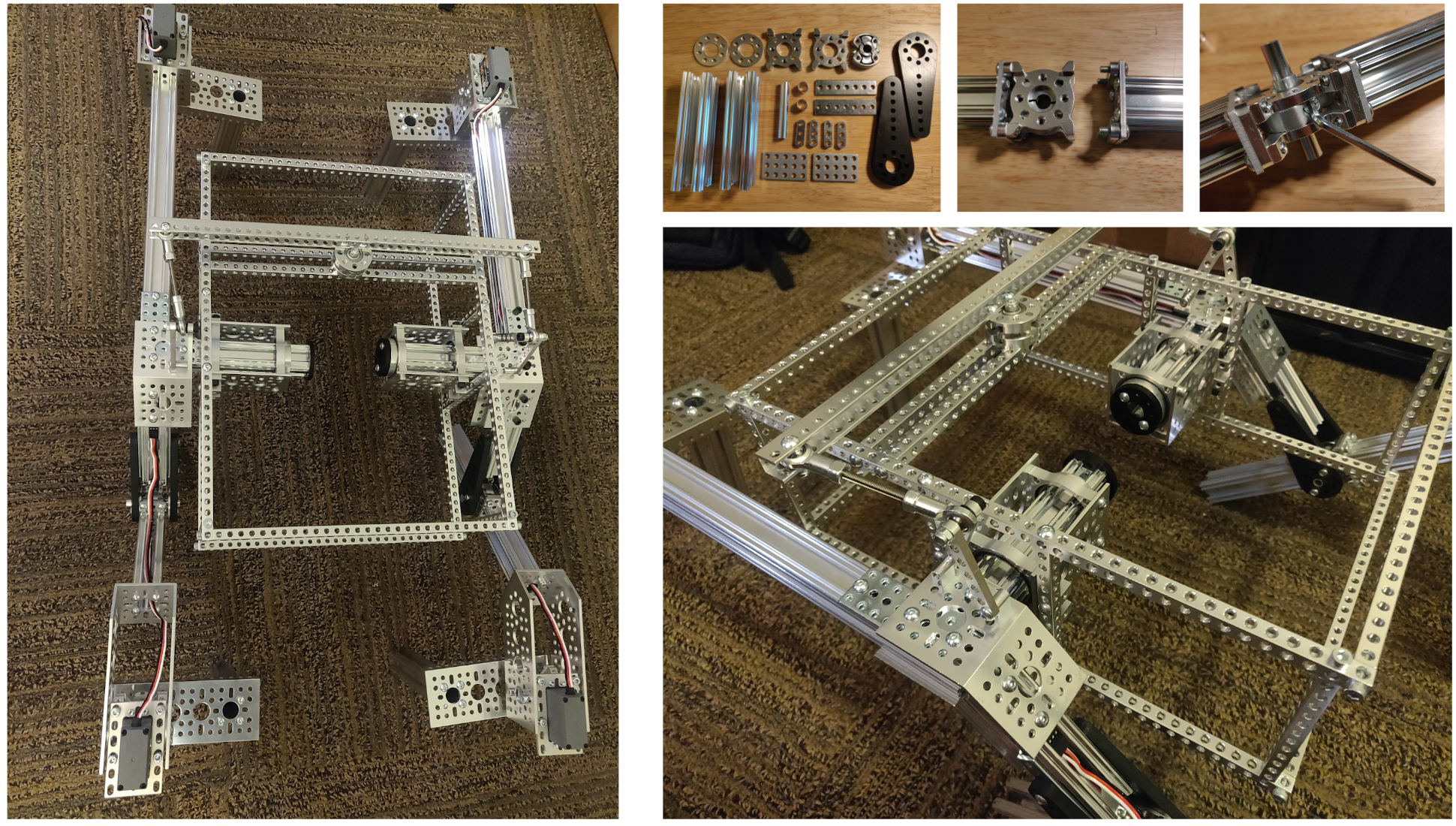
Photo credit
mechanical/images/rover-construction.png
JPL / California Institute of Technology and Open Source Rover contributors · Apache-2.0Unmodified source image.
The image below shows our suggested progression through the mechanical build process for this project. All individual subassemblies are meant to be completely parallelizable, so each individual subassembly could be built on its own at the same time. Once all the subassemblies are finished, there is one mechanical integration process where each of the subassemblies is integrated together to create the final rover body. Along with the pictures in each folder's README document, open the OnShape model so you can see what goes where and spin it around. Note that the OnShape model does not have all screws included to keep the model speedy and light.
Building the subassemblies
Click on the images to get started on a subassembly!
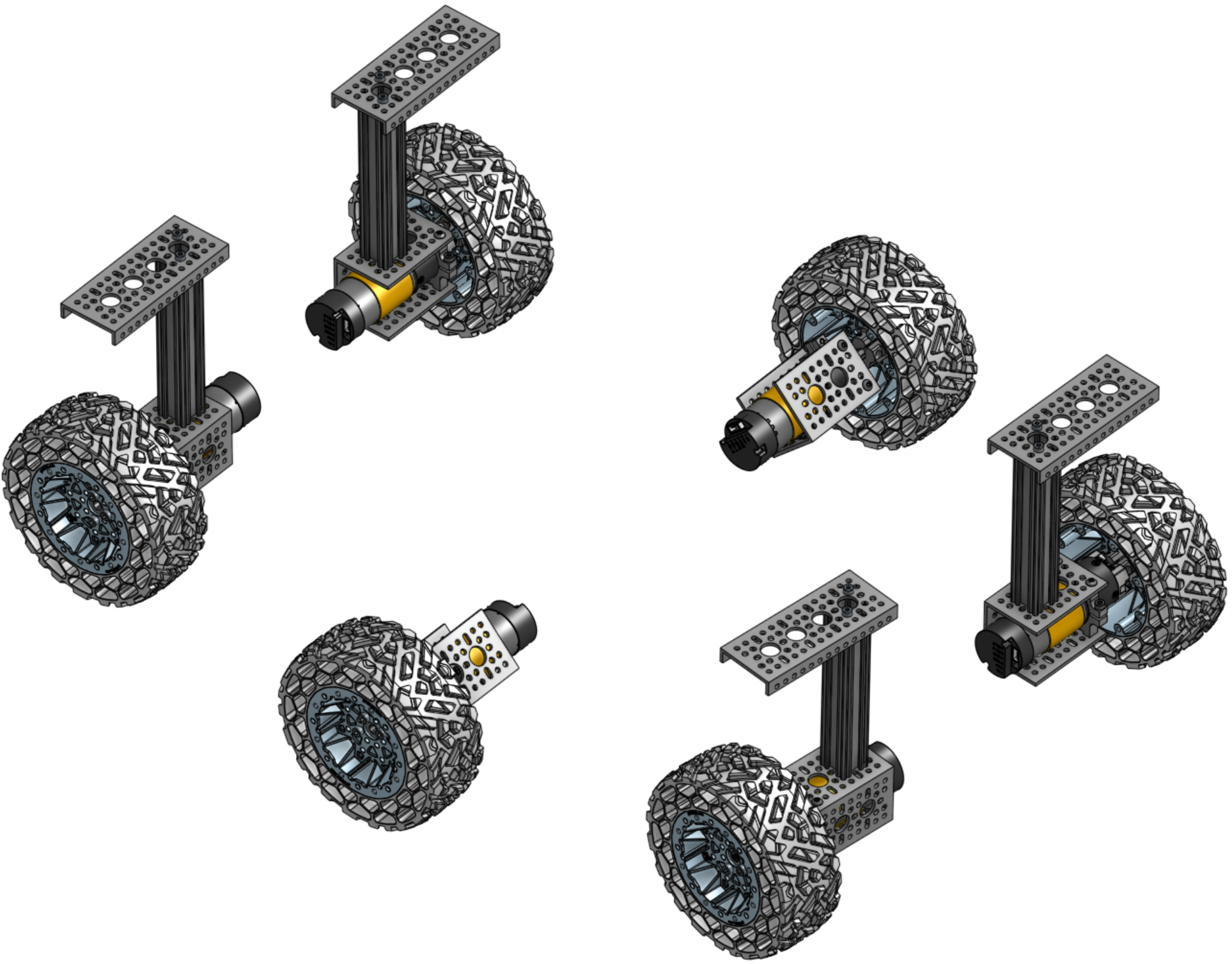 Photo creditmechanical/wheel_assembly/images/wheels.png JPL / California Institute of Technology and Open Source Rover contributors · Apache-2.0Unmodified source image. | 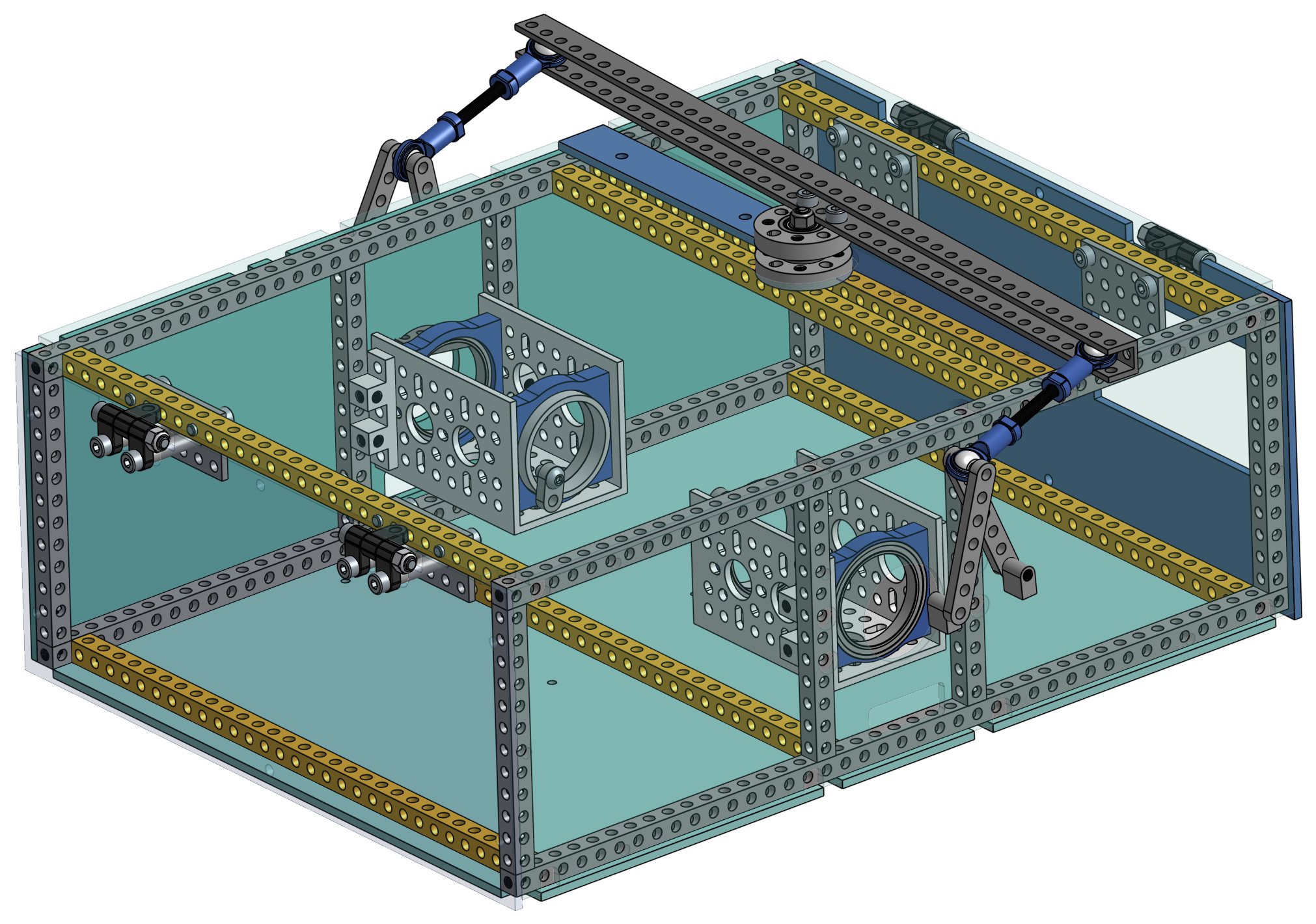 Photo creditmechanical/body/images/body.png JPL / California Institute of Technology and Open Source Rover contributors · Apache-2.0Unmodified source image. | 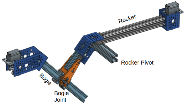 Photo creditmechanical/rocker_bogie/images/rocker_bogie.png JPL / California Institute of Technology and Open Source Rover contributors · Apache-2.0Unmodified source image. |
|---|
Putting it all together
If you haven't already, now is a good time to attach the PCBs to the bottom body plates using the standoffs. The body plates have holes that correspond to where the standoff screws should go.
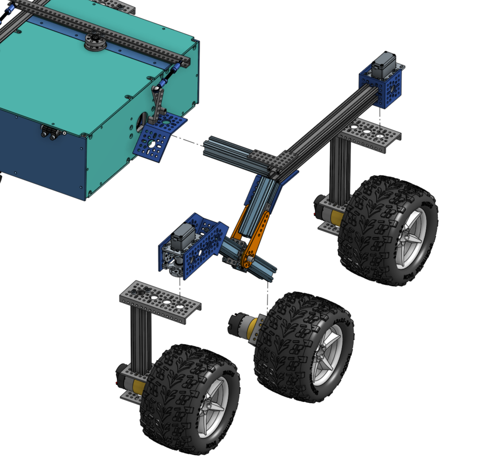
Photo credit
mechanical/images/exploded_mechanical.png
JPL / California Institute of Technology and Open Source Rover contributors · Apache-2.0Unmodified source image.
Inserting the rocker-bogies in the body
Line up the rocker-bogies with the body such that they can be easily inserted. It helps to put the body on a box such that the holes line up with the rocker-bogie axes. Slide a 32mm internal diameter (ID) spacer around the wires and onto the rocker-bogie axis. Then, carefully insert the wires extending from the rocker-bogie axis through the body plate hole and large diameter bearings and into the body, immediately followed by the axis itself. Repeat for the other side.
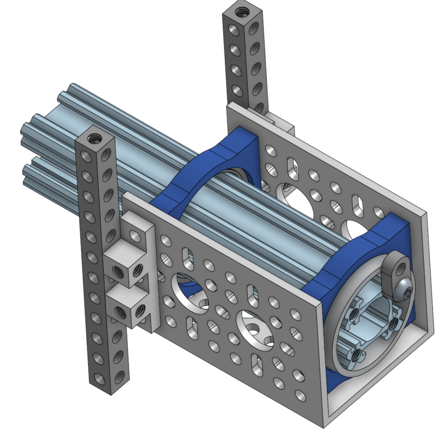
Photo credit
mechanical/images/body_axial_clamp.png
JPL / California Institute of Technology and Open Source Rover contributors · Apache-2.0Unmodified source image.
Secure the body axis to the body using another 32mm ID spacer and flat 2-hole bracket + button screw. Repeat for the other side.
Attaching the differential pivot to the rocker-bogies
Attach the differential pivot legs to the rocker-bogie 45 degree brackets using M4x8 screws. It may be easier to unmount the blocks, attach them to the bracket, then attach the pivot legs to them as shown in the sequence below. A curved pair of needle-nose pliers or a hemostat is helpful to secure the M4x8mm screw while placing the block on the top, as it's hard to reach. The button head screw that attatches to the inside leg is a bit tight.
 Photo creditmechanical/images/dp_reaching_block_screws.jpg JPL / California Institute of Technology and Open Source Rover contributors · Apache-2.0Resized without cropping and converted to WebP. | 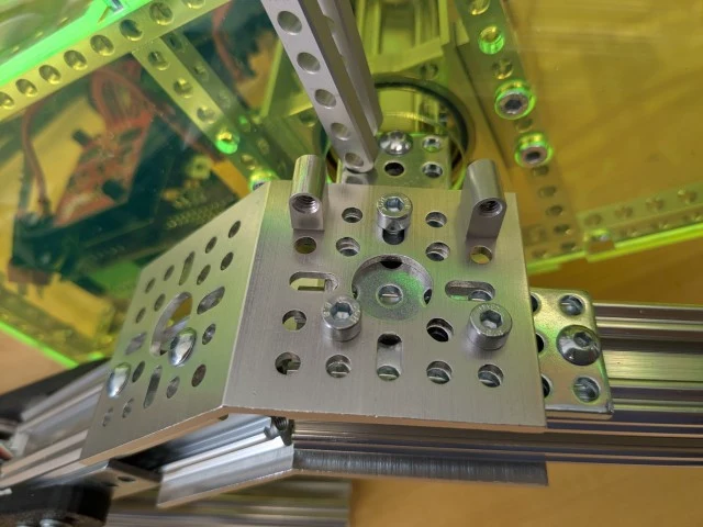 Photo creditmechanical/images/dp_blocks_installed.jpg JPL / California Institute of Technology and Open Source Rover contributors · Apache-2.0Resized without cropping and converted to WebP. |
|---|---|
| Holding the blocks in place | Blocks Installed |
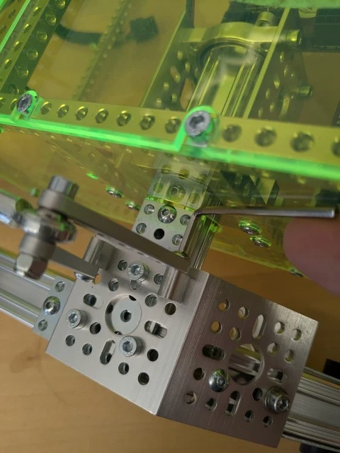 Photo creditmechanical/images/dp_tightening_back.jpg JPL / California Institute of Technology and Open Source Rover contributors · Apache-2.0Resized without cropping and converted to WebP. | 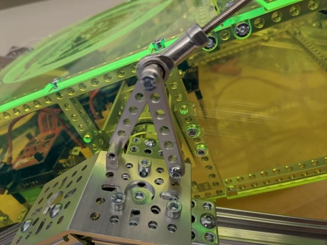 Photo creditmechanical/images/dp_assy_done.jpg JPL / California Institute of Technology and Open Source Rover contributors · Apache-2.0Resized without cropping and converted to WebP. |
|---|---|
| Tightening the back leg | Differential Pivot Installed. |
Attaching the middle drive motors
With the help of someone else, carefully flip the rover over so we can attach the motor assemblies.
Connect the two drive motor U-channels to the rocker bogie middle legs using 3 button screws. Then insert the motor into the U-channel and secure the clamp around the motor's gearbox to the U-channel using 4 socket M4 screws. It helps to have another person around here as well to hold the motors so they don't dangle on the cables.
Attaching the corner assemblies
Using 3 socket M4 screws, attach each corner assembly to the output shaft bracket of the servo. Making sure you connect the right corner assembly to the right side. Flip the rover over again and route the corner cabling through a hole in the bracket holding the servo. The bullet connectors and DuPont connectors from the rocker bogie and corner assemblies should meet here.
tip: Now is a good time to do another connectivity check. Using your multimeter, confirm that each wire connects all the way through.
Maintenance note: The corner servo gearset can sometimes be damaged in operation. See here for a guide on repairing your corner servos.
Finally, insert the PCI-E connectors inside the body and the DuPont connectors for the servo motors into the appropriate receptacles on the PCB. The silk screen lettering on the PCB informs which wire should go where. Once inserted, make sure the rocker-bogies can rotate relatively freely around the body by lifting the wheels up.
If all goes well you're done with the mechanical and electrical stages and you're ready to install the software!
Wheel Assembly
The wheel assembly attaches the wheels to the motors and mounts the motors to the rest of the rocker-bogie suspension system that makes up the robot chassis. These are relatively simple to assemble.
Photo credit
mechanical/wheel_assembly/images/wheels.png
JPL / California Institute of Technology and Open Source Rover contributors · Apache-2.0Unmodified source image.
If you look carefully at the image above, you'll notice that the wheel assemblies are identical, instead of mirror images of each other. For example, notice that the U brackets for the corner wheels are facing different directions on the left and right sides. This is a defect in the OnShape model. When building your rover, you should make the wheel assemblies mirror images of each other - all the openings to the U channel should point to the rear of the rover.
[DollarHobbyz Traxxas Wheels only] Drilling the wheels
If you bought the DollarHobbyz Wheels, you will need to drill some holes through the plastic to allow attaching them to the hubs that fit onto the motor axes. If you have the smaller or bigger Wasteland Wheels from GoBilda, you can skip this step.
The wheel is normally meant to be mounted using one bolt through the middle of the rim. This will not work well in our case as the rover sees very high torque at the wheel and the one-bolt system would be difficult to attach to any part of our system without the wheel slipping. To attach more firmly, we will drill two holes on either side of the original hole where we will mount the motor hub clamp.
Drill at least 2 holes in the wheels such that they can be mounted to the Hyper Hub that attaches to the motor shaft. You'll want to make sure the holes you drill are centered, otherwise the wheel will wobble while driving. Once you've found where to drill the holes, consider using a center punch or small drill bit first before drilling to ensure your drill bit doesn't start 'wandering' before it locks into position. The distance from each hole center to the center of the wheel is
$\sqrt(8^2 + 8^2) \approx 11.3mm$
You can download a drill guide designed to be laser-cut from 3mm acrylic and assembled as shown below to help you drill.
| drill guide | drill guide in use |
|---|---|
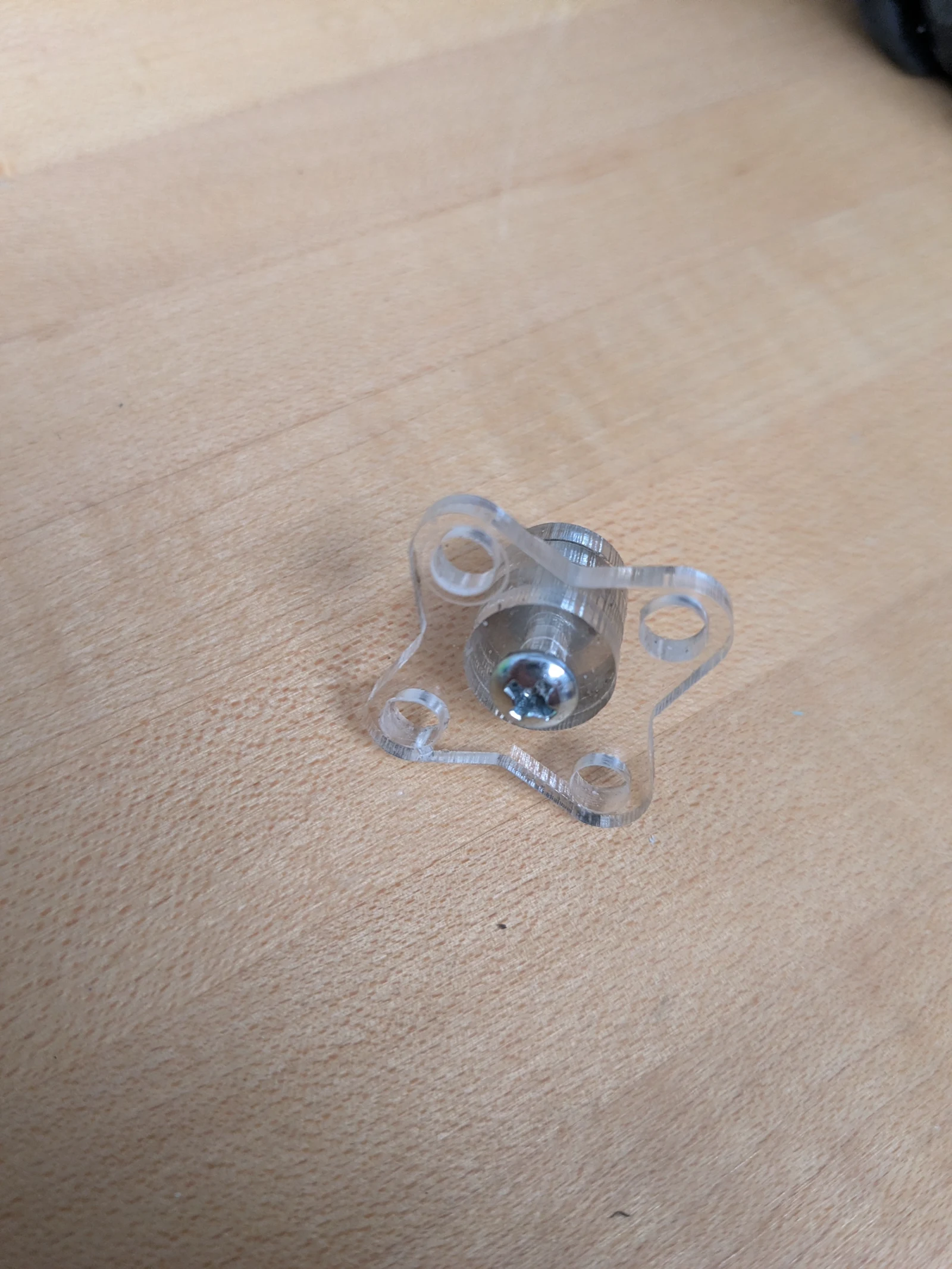 Photo creditmechanical/wheel_assembly/images/wheel_drill_guide.jpg JPL / California Institute of Technology and Open Source Rover contributors · Apache-2.0Resized without cropping and converted to WebP. | 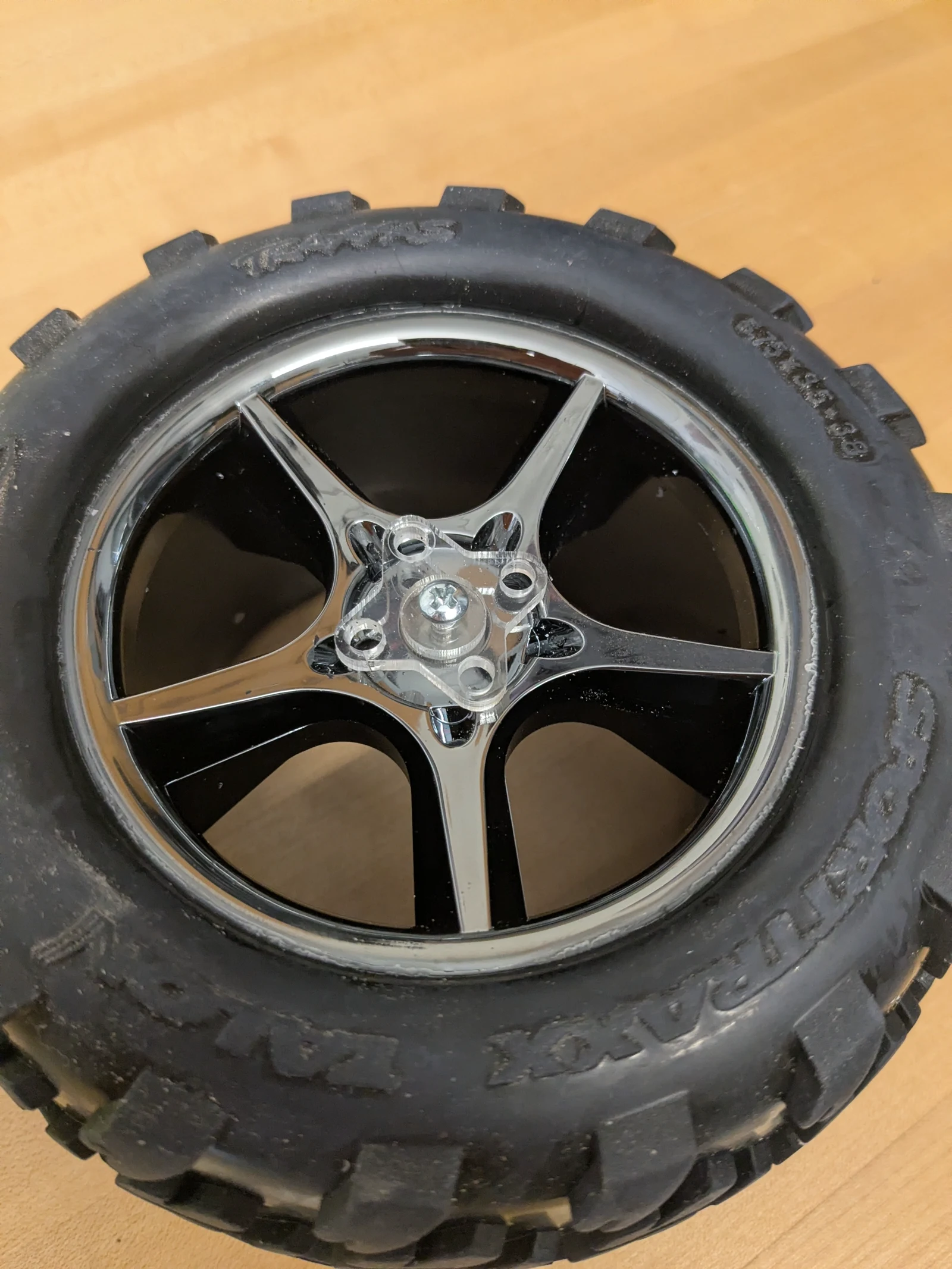 Photo creditmechanical/wheel_assembly/images/wheel_drill_guide_in_use.jpg JPL / California Institute of Technology and Open Source Rover contributors · Apache-2.0Resized without cropping and converted to WebP. |
Assembly
You will need all the parts in the drive wheel assembly parts list.
Assembling the base wheel mounts
Next, we will build the wheel assemblies which are divided into the middle wheels and corner wheel assemblies. We will build 6 identical base wheels and then add slightly more complexity onto 4 of those which will eventually become the corner wheels.
Attach the clamping mount and REX bore hub to the motor. We will adjust their positioning later.
Four corner assemblies
Four of the six drive assemblies you just built will become the corner motors. That only requires two mechanical pieces along with some screws but we'll want to route the wiring through the extruded channel.
The result excluding wiring should look as follows:
| side view without wiring | one of two pairs of corner assemblies |
|---|---|
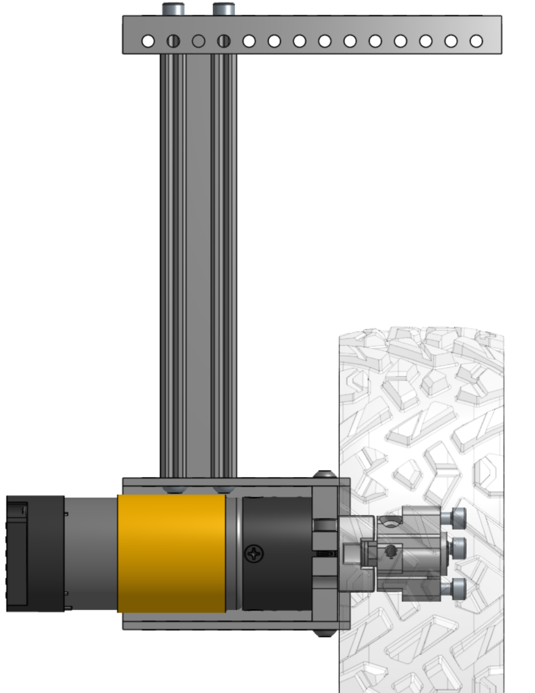 Photo creditmechanical/wheel_assembly/images/corner_side.png JPL / California Institute of Technology and Open Source Rover contributors · Apache-2.0Unmodified source image. | 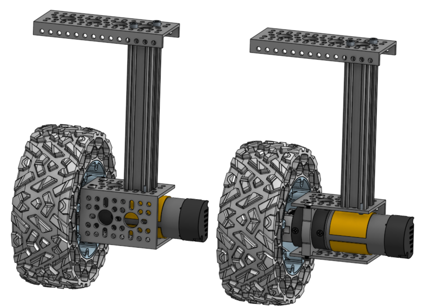 Photo creditmechanical/wheel_assembly/images/corner_mirror.png JPL / California Institute of Technology and Open Source Rover contributors · Apache-2.0Unmodified source image. |
Note that the sides of the rover are mirrored and so you'll be building 2 pairs of similar but not exactly the same subassemblies, as shown in the right image above.
Start by laying out the pieces for each corner so you end up with the 2 mirrored pairs. Install 2911-0014-0001 grommets at the top and bottom of the extruded aluminum goRail, to protect your wires as they go around the corner (not shown in the image below).
Take the DuPont to 4-pin JST encoder pins you created in wiring and route them through the top low-profile U-channel, the extruded aluminum goRail, and finally through the motor bracket. The DuPont connector should be at the top with the 4-pin JST connector at the bottom, ready to be connected to the motor encoder pins.
Route the two motor power cables through the same parts in the opposite direction. Finally, screw the parts together using 3 or 4 M4x6mm button screws inside the U-channel and using 3 or 4 M4x8mm socket screws at the top. Don't tighten the screws too much yet as this will allow you to adjust wiring. Place a clamping motor mount on the end of the U-channel farthest from the goRail with 4 M4x6mm button screws.
Adjust the wiring so there is minimal wiring inside the channel. Make sure to protect your wiring from chafing or cutting from the sharp aluminum edges with split sleeve or other shielding! Be careful when adjusting wires so to not damage the plastic shielding and potentially create shorts.
Optional Wiring Arrangement
There is not a lot of clearance between the U-channel and the motor for the wiring to pass through, especially when wrapping the cables in a sleeve. You can choose to cut a notch in the extruded aluminium goRail just above the U-channel, as shown below.
| goRail notched | corner assembly step 2 | corner assembled |
|---|---|---|
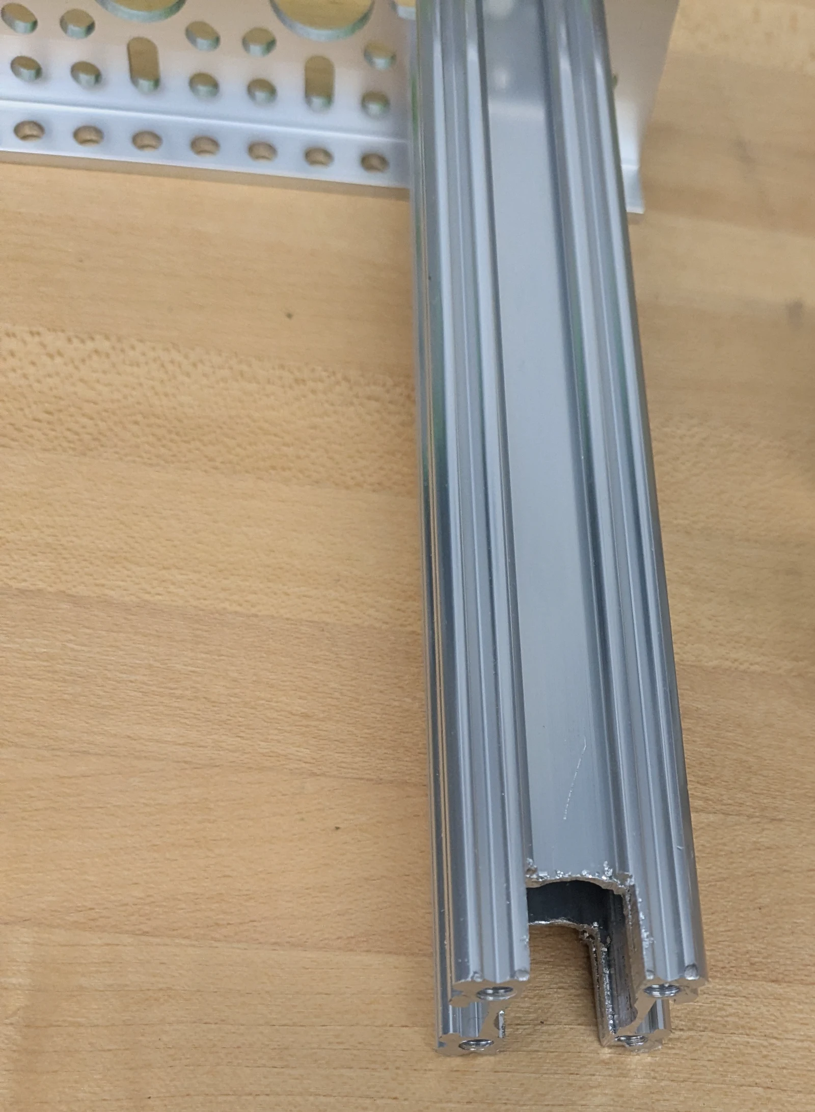 Photo creditmechanical/wheel_assembly/images/corner_notch.jpg JPL / California Institute of Technology and Open Source Rover contributors · Apache-2.0Resized without cropping and converted to WebP. | 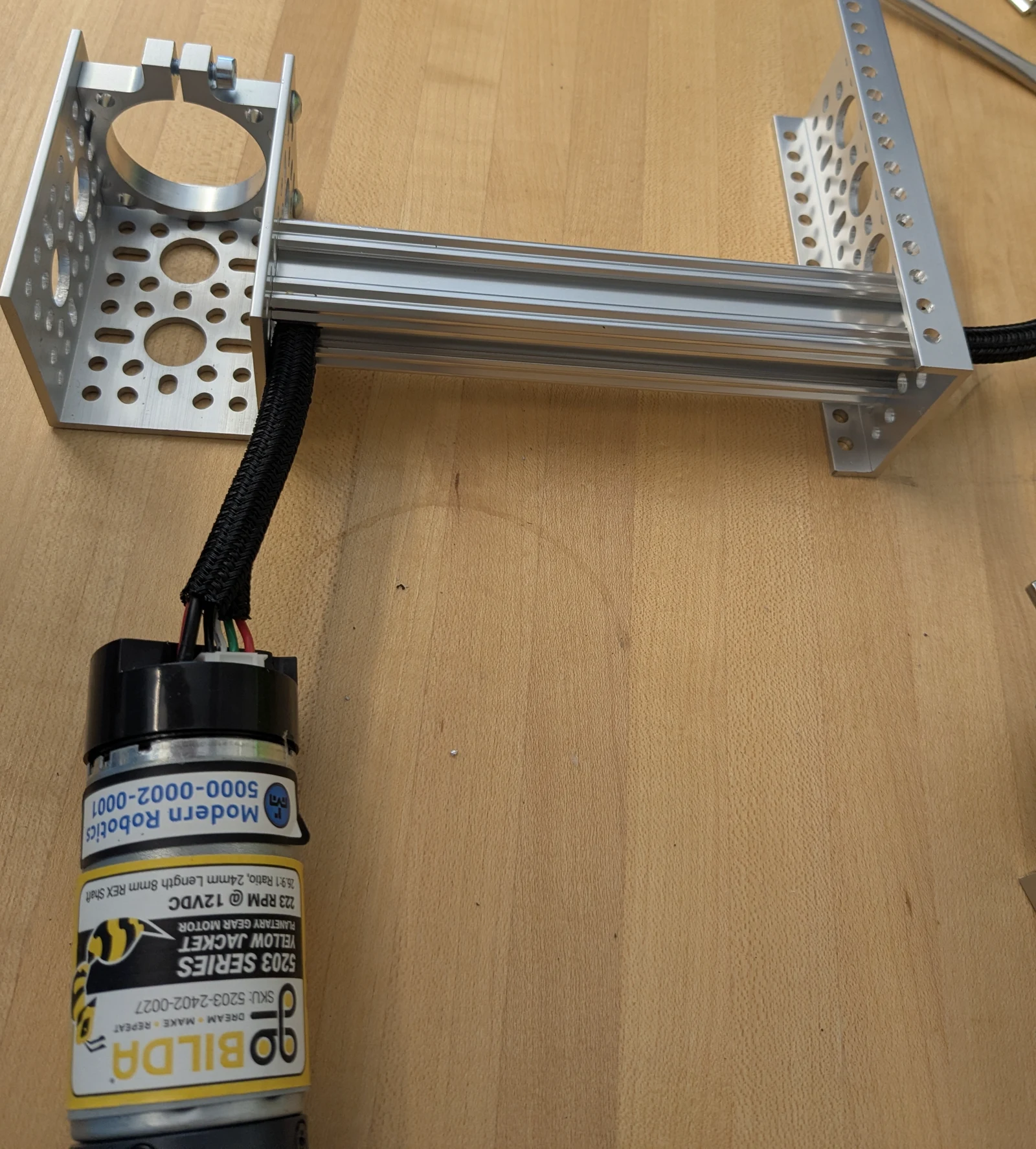 Photo creditmechanical/wheel_assembly/images/corner_wnotch_step2.jpg JPL / California Institute of Technology and Open Source Rover contributors · Apache-2.0Resized without cropping and converted to WebP. | 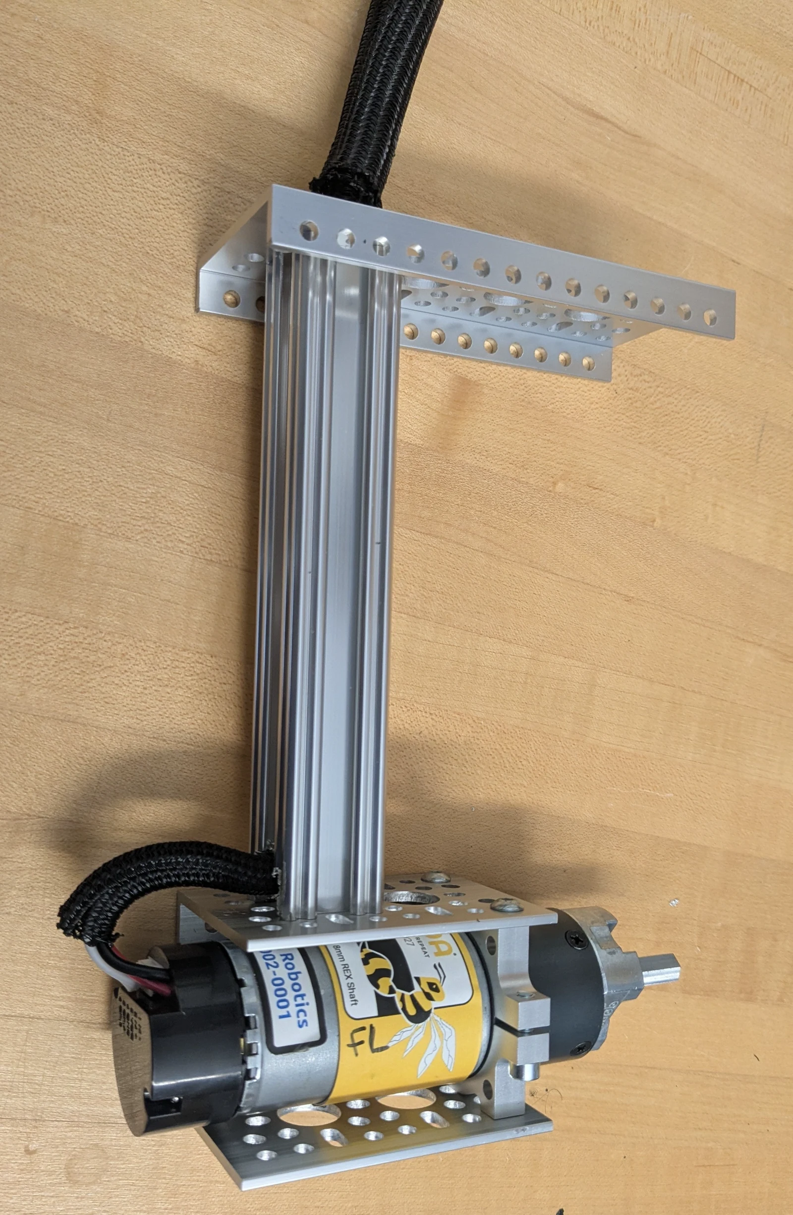 Photo creditmechanical/wheel_assembly/images/corner_assembled_wnotch.jpg JPL / California Institute of Technology and Open Source Rover contributors · Apache-2.0Resized without cropping and converted to WebP. |
Repeat this for the three other corner assemblies.
Assembled corners
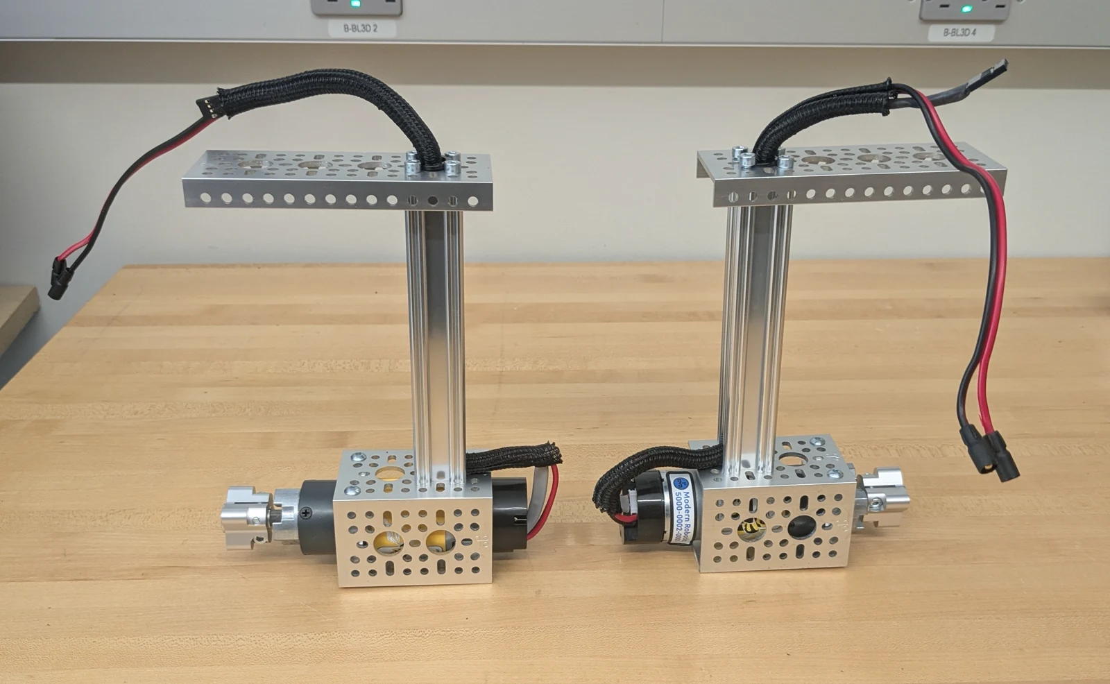
Photo credit
mechanical/wheel_assembly/images/two_corners_assembled.jpg
JPL / California Institute of Technology and Open Source Rover contributors · Apache-2.0Resized without cropping and converted to WebP.
Main Body Assembly
The body is the housing of all the electronics for the rover and acts as the attachment point for the differential pivot and the body axis that the rocker-bogies on either side connect to.
Photo credit
mechanical/body/images/body.png
JPL / California Institute of Technology and Open Source Rover contributors · Apache-2.0Unmodified source image.
Assemble the body frame
Gather the pieces from the parts list for the body.
- 4x 41 hole, 328mm square beams
- 5x 29 hole, 232mm square beams
- 8x 12 hole, 96mm square beams
- 26x M4x16 socket screws
Bottom Frame
Connect 2x 29 hole and 2x 41 hole beams with M4x16 screws as shown. Be sure to attach the cross beams 1 hole in on the long beams. Insert 1 29 hole beam into hole #16, counting from the front of the rover. (TODO: Update image to move crossbar.)
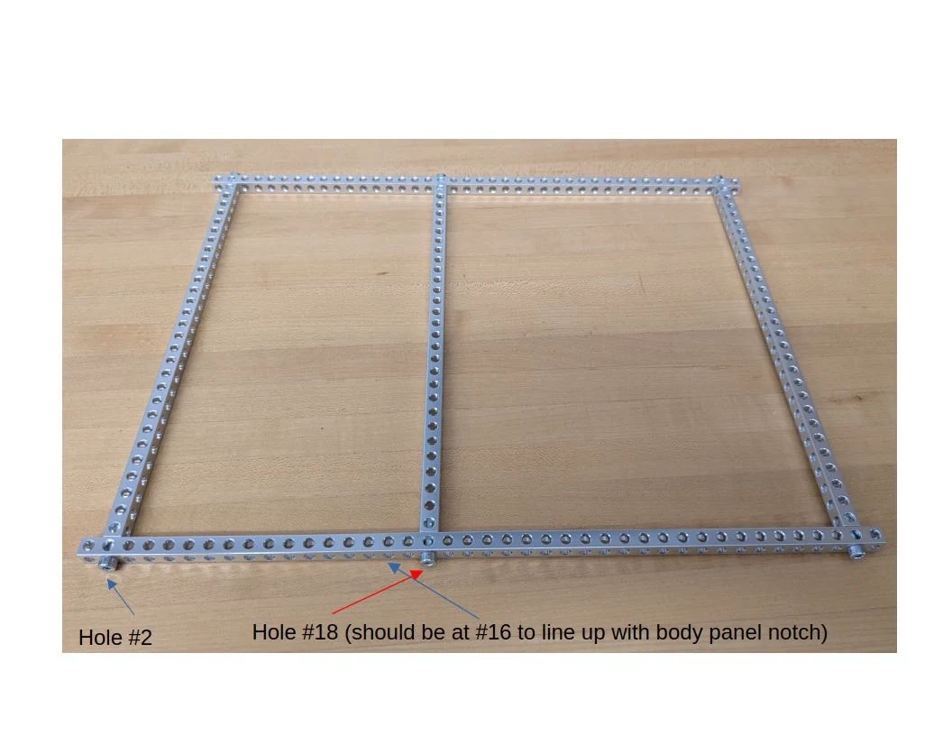
Photo credit
mechanical/body/images/body_base.jpg
JPL / California Institute of Technology and Open Source Rover contributors · Apache-2.0Resized without cropping and converted to WebP.
Top Frame
Connect 2x 29 hole and 2x 41 hole beams with M4x16 screws as shown.
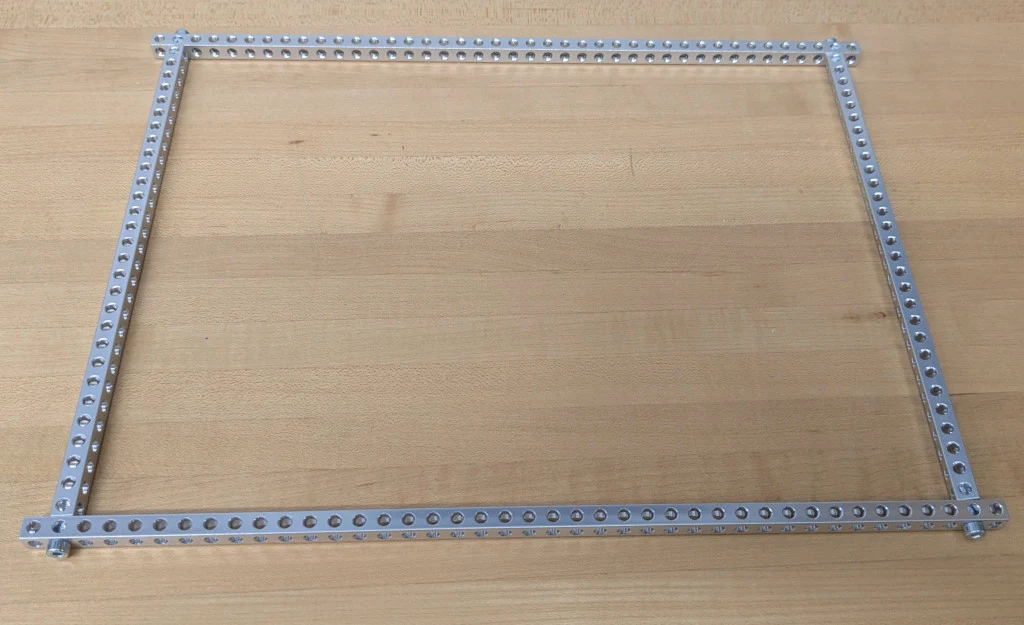
Photo credit
mechanical/body/images/body_top.jpg
JPL / California Institute of Technology and Open Source Rover contributors · Apache-2.0Resized without cropping and converted to WebP.
Verticals
Connect 8x 12 hole beams along the long edges in holes #1, 17, 25, and 41 on both sides. (TODO: Update image to move crossbar.)
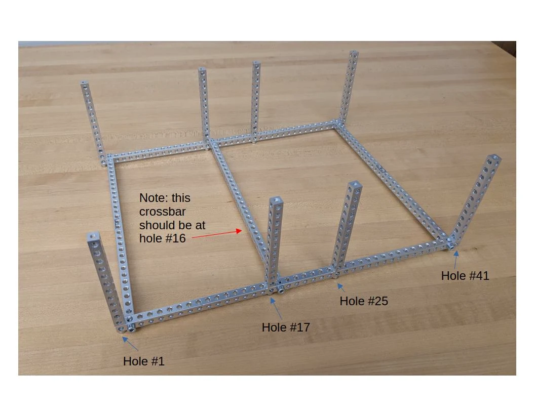
Photo credit
mechanical/body/images/body_vertical.jpg
JPL / California Institute of Technology and Open Source Rover contributors · Apache-2.0Resized without cropping and converted to WebP.
Assemble the bearing support structures that connect to the rocker-bogie
Make two of these and connect them to the sides of the body. They should be installed exactly in the middle, which means that you're going to connect each side to the 17th hole on the long 41-hole beams on the top and bottom of the body frame. Use the M4 16mm socket screws. Use M4x12 screws on the end toward the outside of the rover and M4x8 screws on the end toward the center of the rover end.
The bearings have a flat side and a 'hollow' side. The hollow sides should both be pointing to the center of the rover side, as shown in the image.
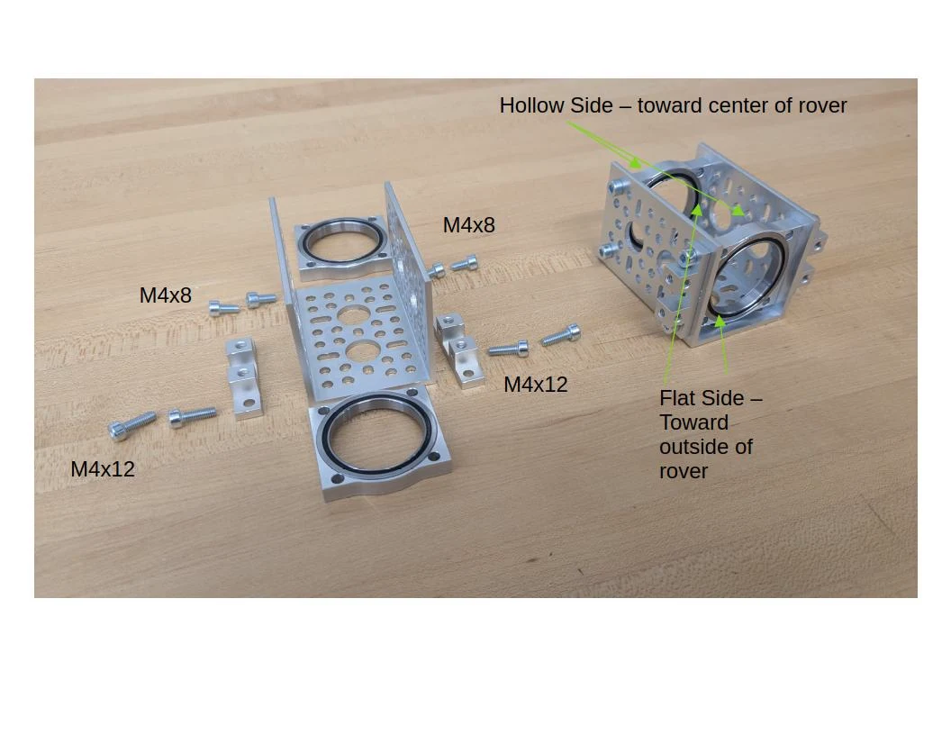
Photo credit
mechanical/body/images/body_bearing_supports.jpg
JPL / California Institute of Technology and Open Source Rover contributors · Apache-2.0Resized without cropping and converted to WebP.
Now, install the supports on the 6th hole from the top of the 12 hole beam, and the 5th hole from the bottom. If it's a bit tight, loosen up the verticals until all the screws are started, then tighten all of them after.
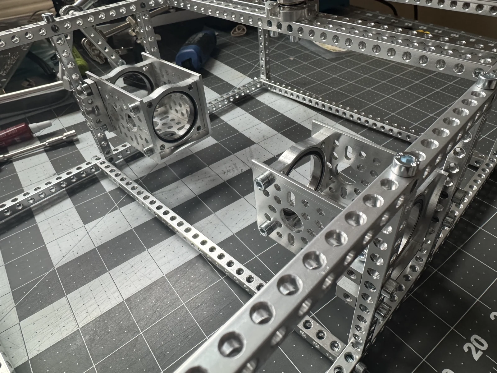
Photo credit
mechanical/body/images/rocker-bogie-sleeves.jpeg
JPL / California Institute of Technology and Open Source Rover contributors · Apache-2.0Resized without cropping and converted to WebP.
Install the hinges for the top body plates
You will need the 20 or 22mm M4 standoffs, the 3x5 hole plate, the hinge assembly (assemble following the instructions on GoBilda, orientation matters).
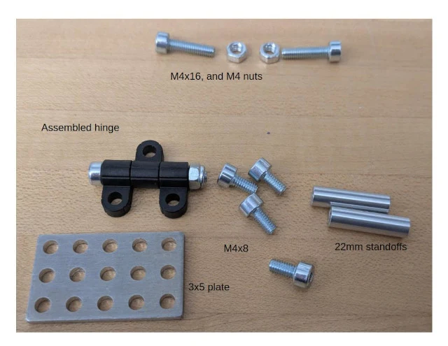
Photo credit
mechanical/body/images/hinge_parts.jpg
JPL / California Institute of Technology and Open Source Rover contributors · Apache-2.0Resized without cropping and converted to WebP.
First, attach the standoffs to the 3x5 plate with M4x8mm socket head screws
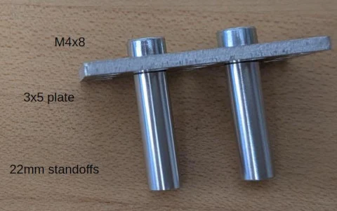
Photo credit
mechanical/body/images/hinge_step1.jpg
JPL / California Institute of Technology and Open Source Rover contributors · Apache-2.0Resized without cropping and converted to WebP.
Then, attach the plate to the top front and top rear beam, leaving 4 holes to the outside of the plate.
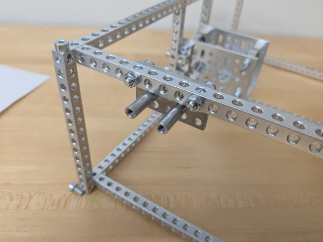
Photo credit
mechanical/body/images/hinge_step3.jpg
JPL / California Institute of Technology and Open Source Rover contributors · Apache-2.0Resized without cropping and converted to WebP.
Finally, attach the hinges to the standoffs, facing the flat part of the plastic to the outside and top as shown, with M4x8 screws
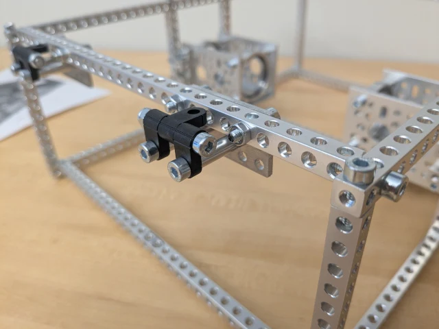
Photo credit
mechanical/body/images/hinge_installed.jpg
JPL / California Institute of Technology and Open Source Rover contributors · Apache-2.0Resized without cropping and converted to WebP.
You will attach the body plate to the top part of the hinge in a later step.
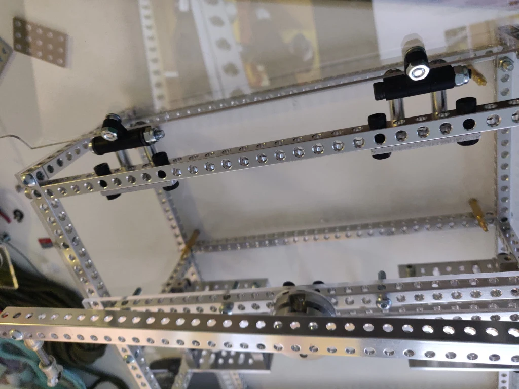
Photo credit
mechanical/body/images/hinges.jpg
JPL / California Institute of Technology and Open Source Rover contributors · Apache-2.0Resized without cropping and converted to WebP.
Make the differential pivot
The Differential Pivot helps to offload forces from one side of the rover to the other while climbing. The differential pivot is crucial in the rocker-bogie suspension system and is designed to help keep all 6 wheels on the ground at all times. It also allows a second attachment point for the body so that it does not freely rotate about the center axes that run through it and connects the two rocker-bogies.
Gather the parts
You'll need the parts shown below.
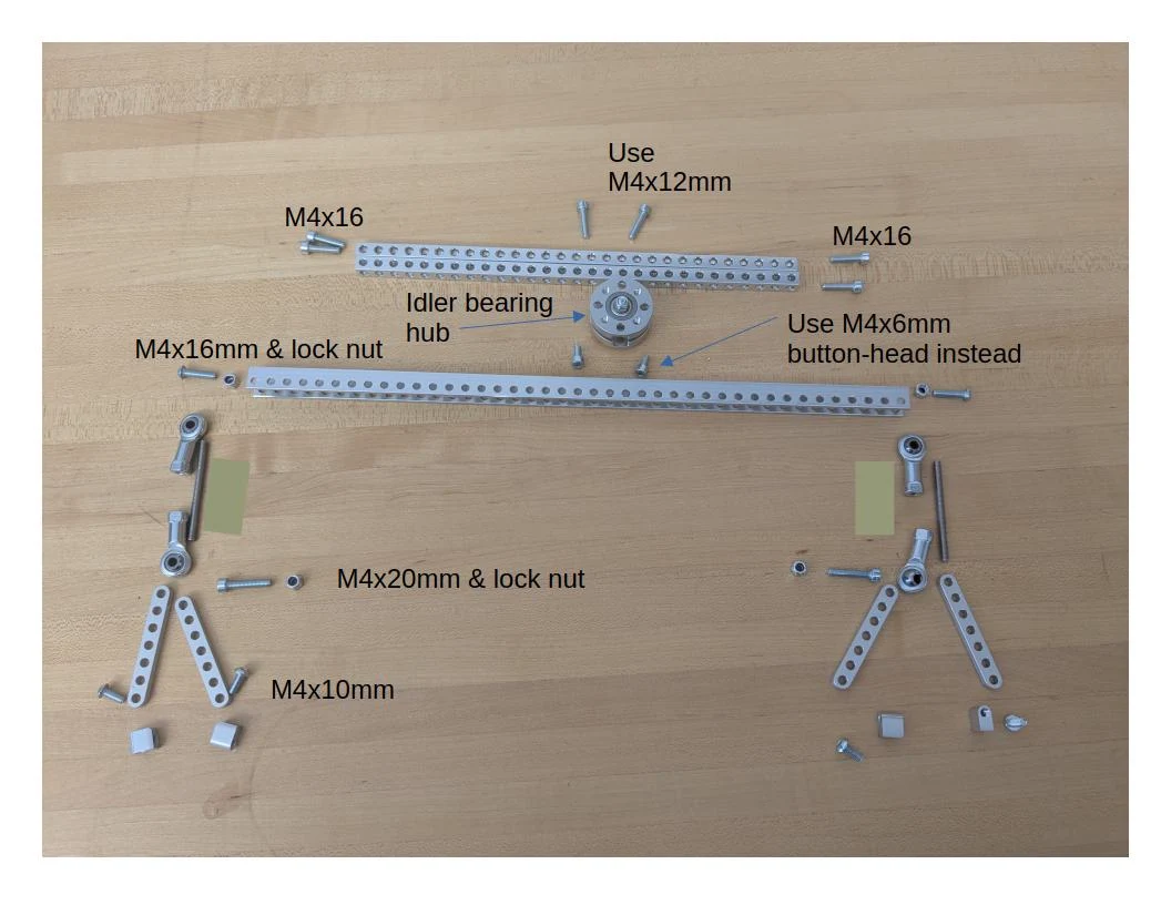
Photo credit
mechanical/body/images/diff_parts.jpg
JPL / California Institute of Technology and Open Source Rover contributors · Apache-2.0Resized without cropping and converted to WebP.
TODO: update image to show M4x6mm button screws instead of the M4x6mm socket head screws show here (and in the CAD)
Assemble the idler bearing hub following the instructions on GoBilda.
Connect the block mount to the 7-hole linkage using M4x10mm button-head screws. Connect the 20mm threaded rod to a steel ball linkage on each end to create two turnbuckles.
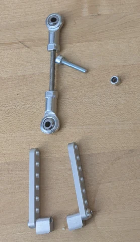
Photo credit
mechanical/body/images/diff_step1.jpg
JPL / California Institute of Technology and Open Source Rover contributors · Apache-2.0Resized without cropping and converted to WebP.
Connect the turnbuckle to the 7-hole bar linkages with an M4x20 socket head screw and lock nut, and to the second hole from the end of the U channel with an M4x16 button head screw and lock nut. Repeat for other side.
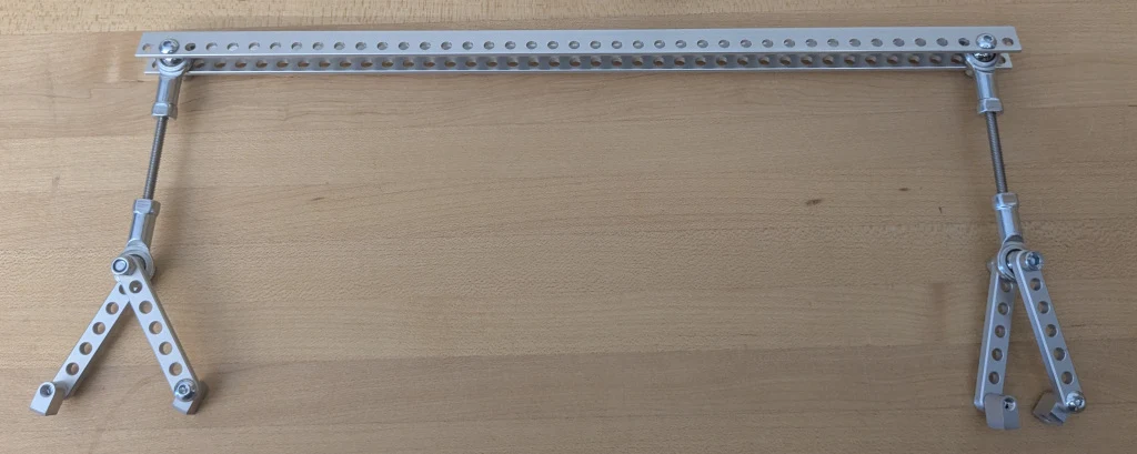
Photo credit
mechanical/body/images/diff_step2.jpg
JPL / California Institute of Technology and Open Source Rover contributors · Apache-2.0Resized without cropping and converted to WebP.
Connect the differential pivot (the whole assembly) to the idler bearing hub with two M4x6 button-head screws
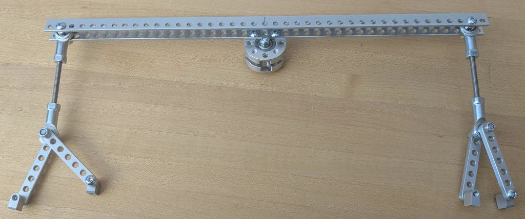
Photo credit
mechanical/body/images/diff_mount_top.jpg
JPL / California Institute of Technology and Open Source Rover contributors · Apache-2.0Resized without cropping and converted to WebP.
Add 2x 29 hole, 232mm square beams in holes #28 and 30 from the front, on the longer 41 hole, 328mm beams, using M4x16mm socket head screws. Mount the idler bearing hub to the crossbars with M4x12mm socket head screws as shown.
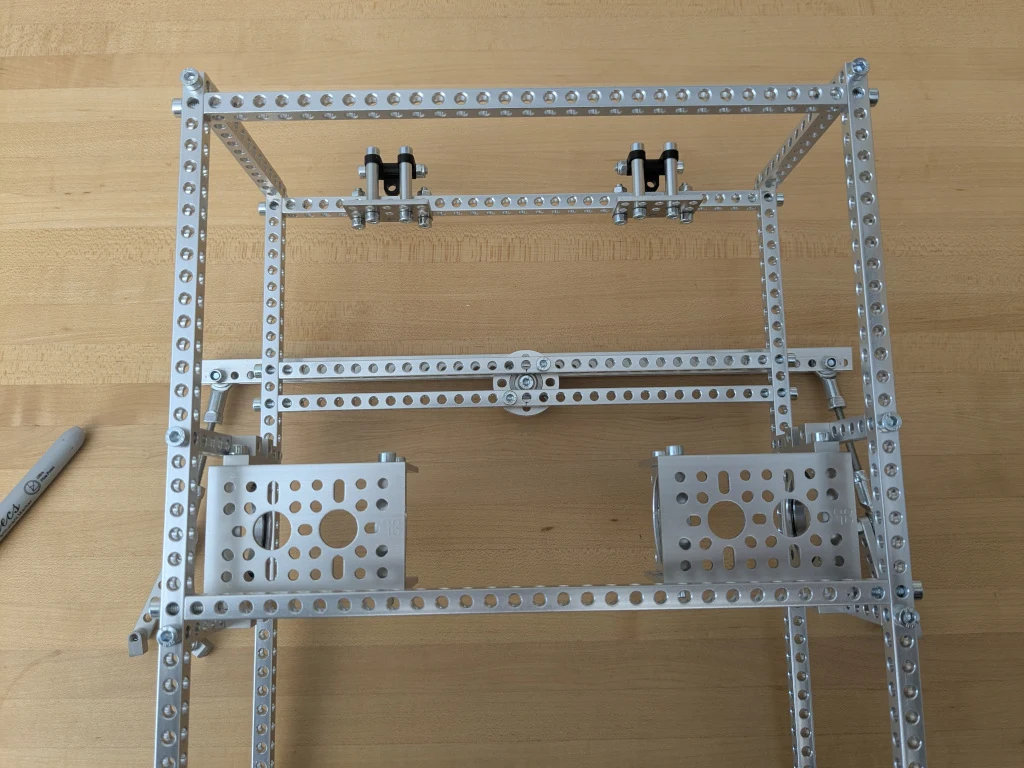
Photo credit
mechanical/body/images/diff_mount_bot.jpg
JPL / California Institute of Technology and Open Source Rover contributors · Apache-2.0Resized without cropping and converted to WebP.
The differential pivot should be able to freely rotate around the body. We'll attach the side of the differential pivot to the rocker-bogies later.
Install the laser cut body plates
Use M8x16 button head screws because of their lower profile along with nuts on the inside so the screws don't fall out while driving. If you've completed the PCB assemblies yet, you can attach them to the bottom body plate already, but you can also do this later.
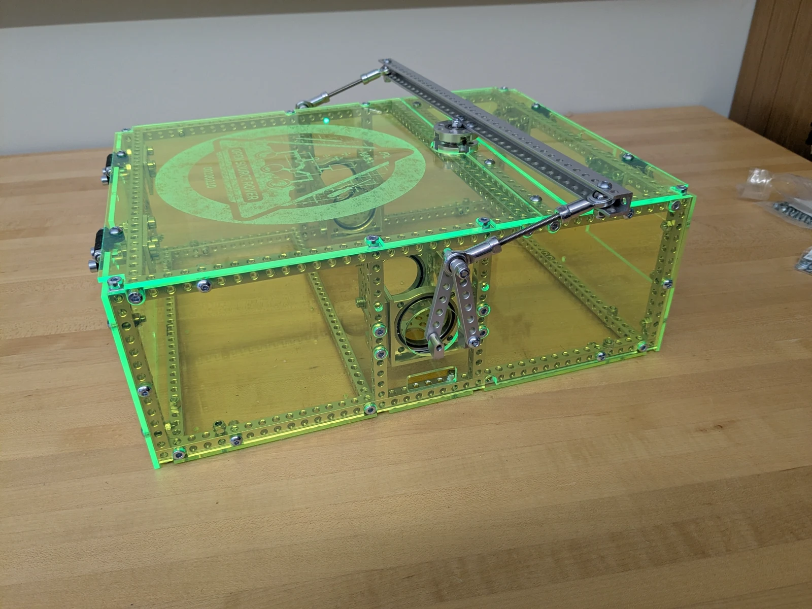
Photo credit
mechanical/body/images/body_closed.jpg
JPL / California Institute of Technology and Open Source Rover contributors · Apache-2.0Resized without cropping and converted to WebP.
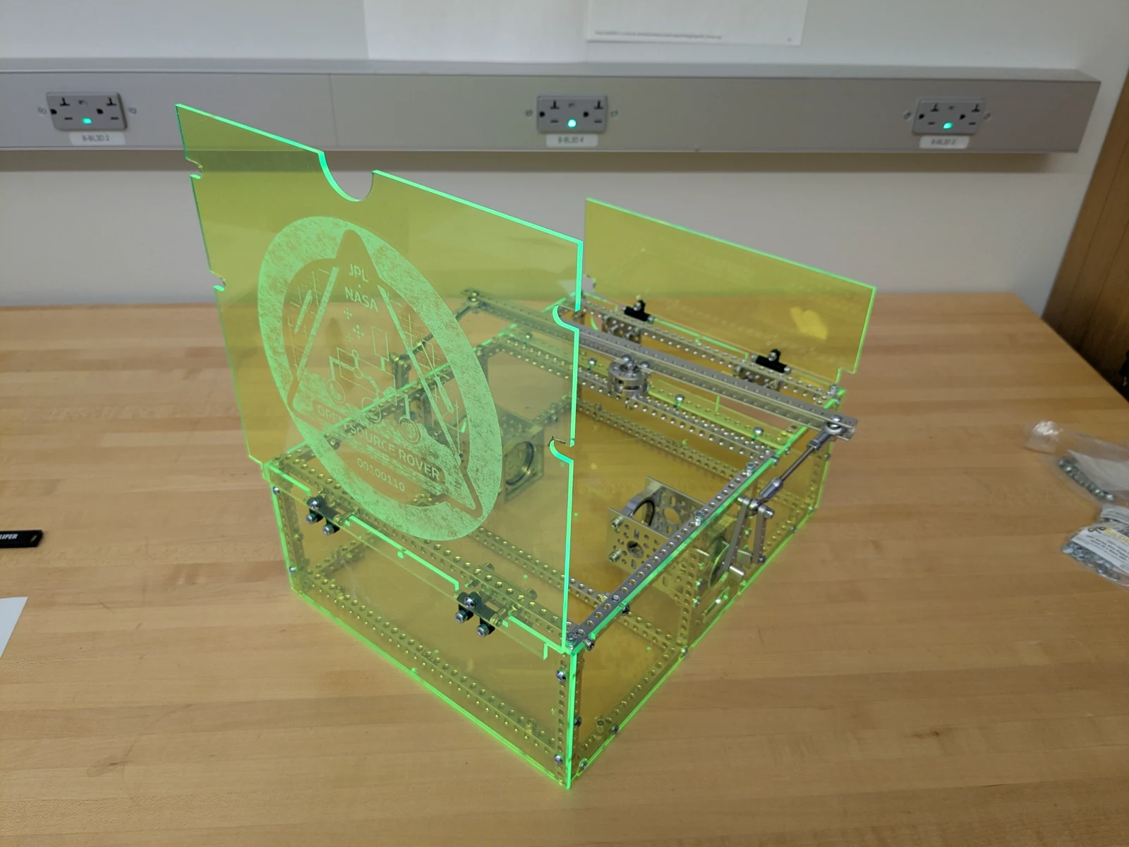
Photo credit
mechanical/body/images/body_open.jpg
JPL / California Institute of Technology and Open Source Rover contributors · Apache-2.0Resized without cropping and converted to WebP.
Laser cut parts
Contains the files required to cut the body plates.
Note: The side plates and 'gap slats' are identical and so only one file is included. Make sure you include two side plates and two gap slats when you get it laser cut!
Ordering
Various companies will allow you to order laser cut parts with them with fast turnaround times. Some options:
Formats provided:
- 2D: DXF and SVG
- Engrave: PDF
You are free to pick different materials and colors. Using SendCutSend, your cart should look something like this:
Shareable carts
You can skip the DXF upload steps when using SendCutSend by using this premade cart.
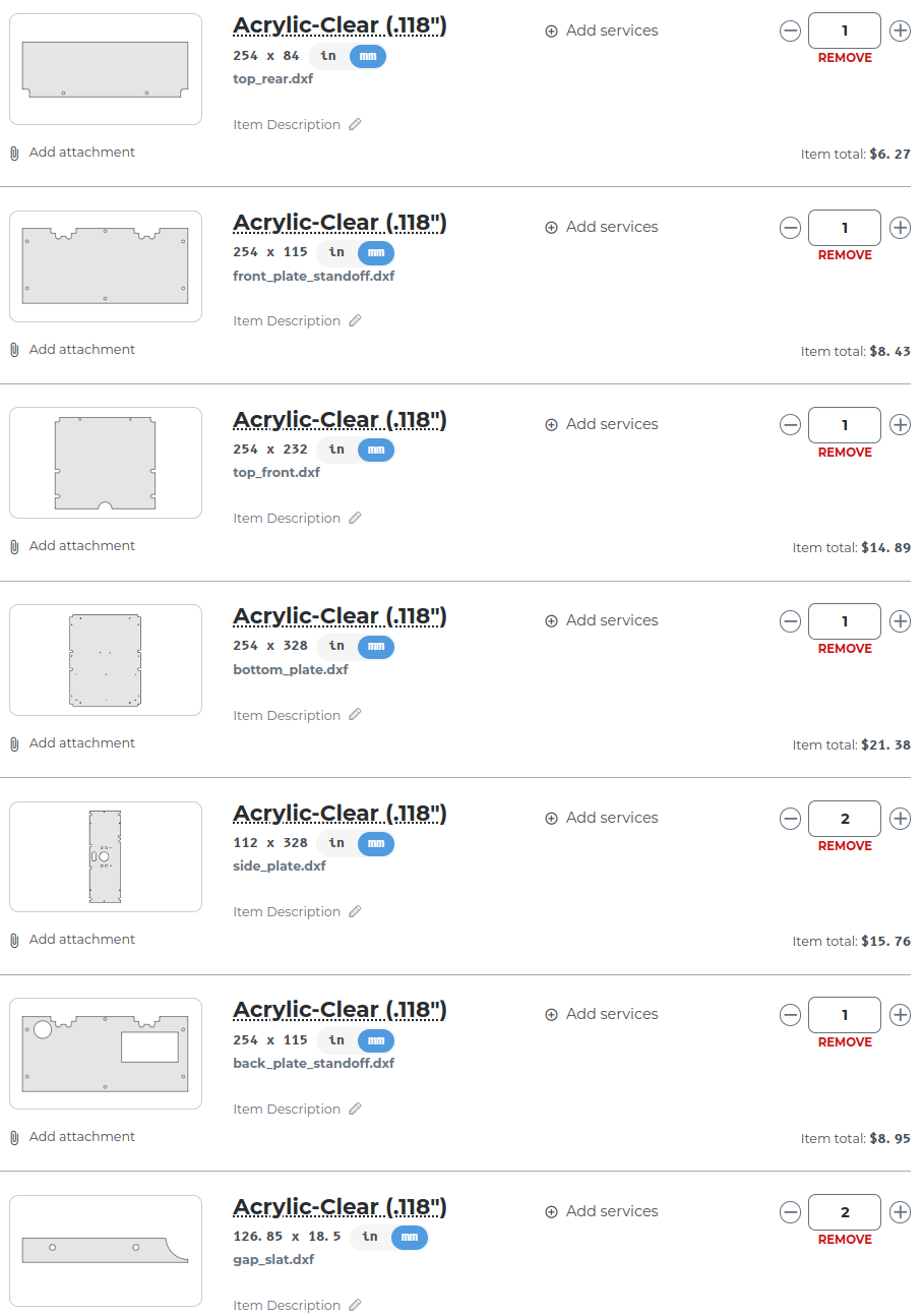
Photo credit
mechanical/body/laser_cut_parts/osr_sendcutsend_cart.png
JPL / California Institute of Technology and Open Source Rover contributors · Apache-2.0Unmodified source image.
Optional: Engrave the mission patch
Front plates with the Rover patch logo as an engraving have been included as PDF files. There are two versions. The 'Opaque' version requires that the logo be engraved on the top surface of the material. The 'Clear' version allows the engraving to be on the bottom side so the top surface is smooth.
Changelog
- Use 22mm standoffs.
- All holes have been made slightly larger to better accomodate the M3 screws. The size of the switch hole on the rear plate is also slightly larger.
- Some of the holes on the side and bottom plates have been moved to simplify assembly.
Rocker-Bogie Suspension
The Rocker-Bogie is the suspension system that enables the rover to climb aggressive obstacles. The design allows all 6 wheels to be in contact with the ground as much as possible, increasing traction. The suspension system on a typical consumer vehicle can traverse obstacles about half the height of one wheel; the Rocker-Bogie suspension system can traverse obstacles over 2 times the height of the wheel.
Photo credit
mechanical/rocker_bogie/images/rocker_bogie.png
JPL / California Institute of Technology and Open Source Rover contributors · Apache-2.0Unmodified source image.
Features
- Modular link lengths give the ability to customize rover geometry
- Optimized for climbing in the forwards direction
- Rigid support structure resists lateral bending/twisting about the Bogie joint
Mechanical Interface/Attachments to Rover
- Servo block output shafts connect to corner motor assemblies
- rocker-bogie connects to the body axis clamp via two brackets that are detailed in the body assembly section
- middle drive motor connects to the extruded shaft at the bottom
Assembly
You will be creating two almost identical assemblies. Below instructions are for one side. We recommend building one side first rather than trying to build both sides in parallel, that way you'll be able to make the other side faster. Before you start building, familiarize yourself with the details of this assembly, in particular because you'll be building two assemblies that are mirrorred. Specifically, you'll want the open slits on the bogie to be facing the same side:
| close up showing slits |
|---|
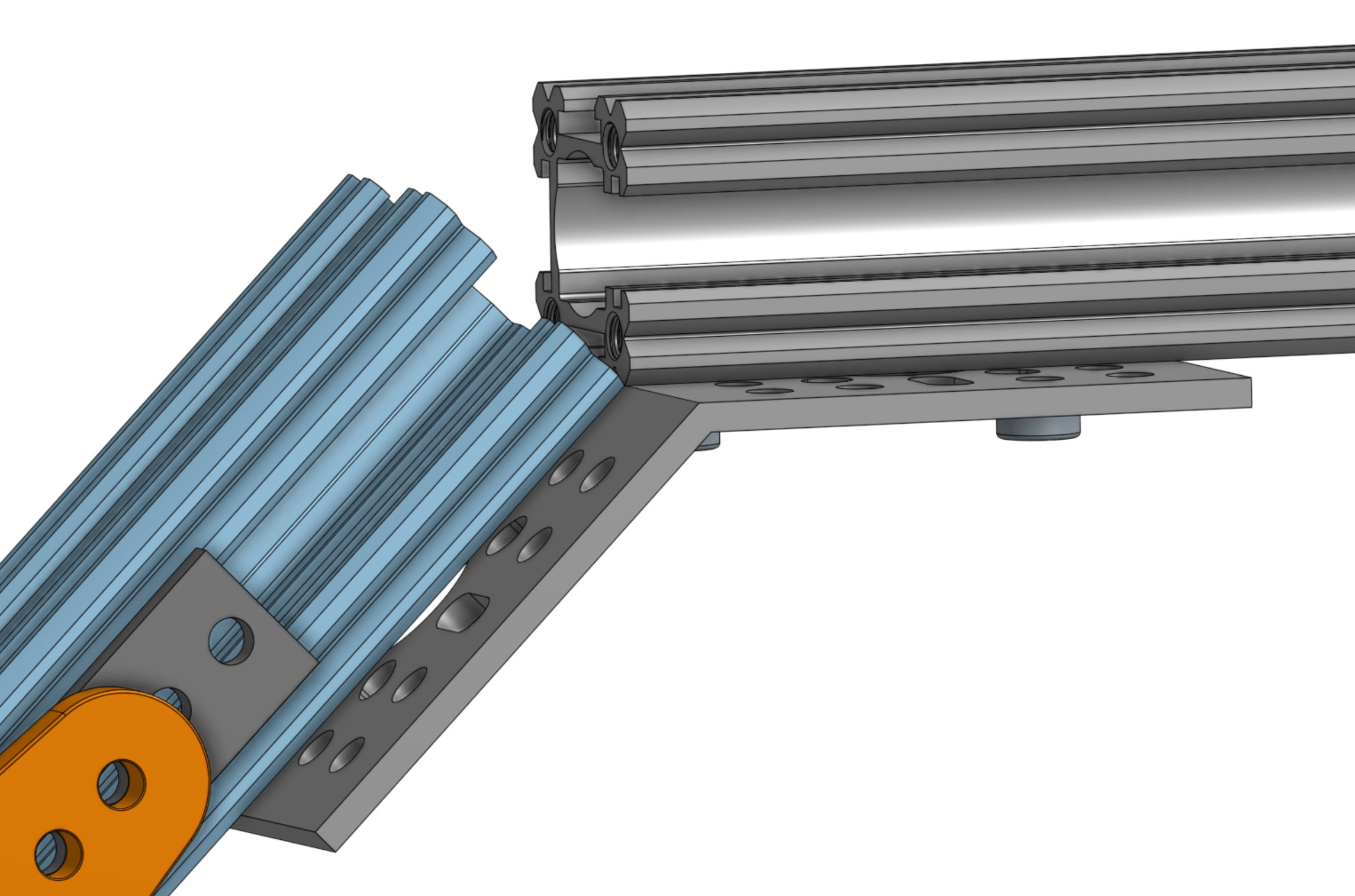 Photo creditmechanical/rocker_bogie/images/slit_direction_closeup.png JPL / California Institute of Technology and Open Source Rover contributors · Apache-2.0Unmodified source image. |
Creating the rocker-bogie joint
First, gather the parts you'll need for the joint that connects the rocker to the bogie.
| Joint Parts |
|---|
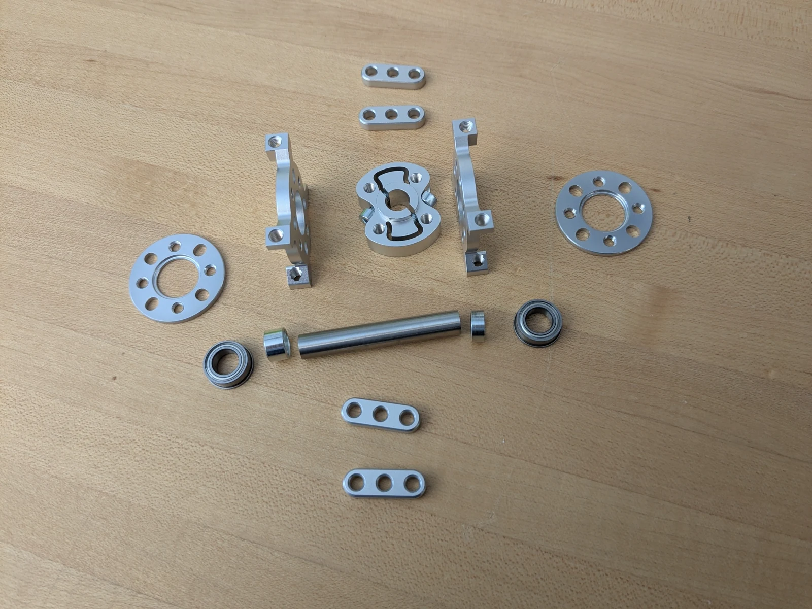 Photo creditmechanical/rocker_bogie/images/joint_parts.jpg JPL / California Institute of Technology and Open Source Rover contributors · Apache-2.0Resized without cropping and converted to WebP. |
Assemble the joint following the steps below. Since the clamp in the middle isn't symmetric and protrudes on one side, two spacers of different lengths are used. You can see this in the top left image. You'll use spacer 1522-0010-0040 of length 4mm on the side of the clamp that has the protrusion, while on the other, flat side, you'll use spacer 1514-0010-0060 of length 6mm. This creates a tight assembly that prevents the joint from flexing from side to side.
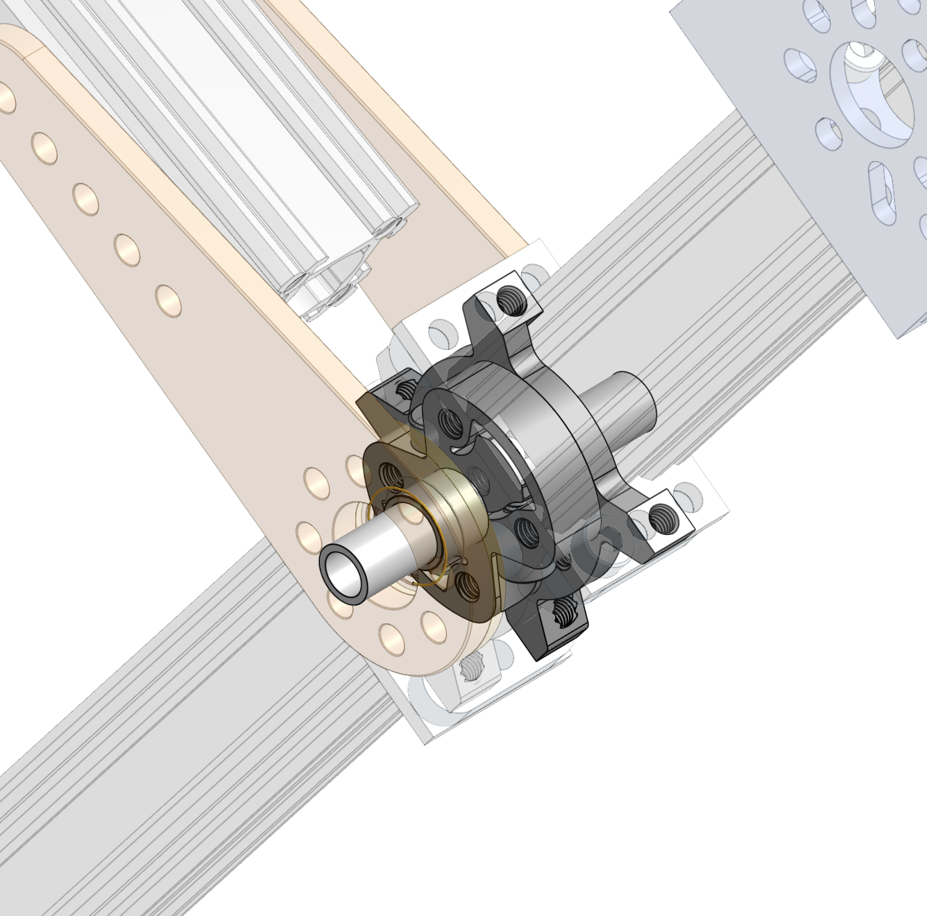 Photo creditmechanical/rocker_bogie/images/pivot_start.png JPL / California Institute of Technology and Open Source Rover contributors · Apache-2.0Unmodified source image. | 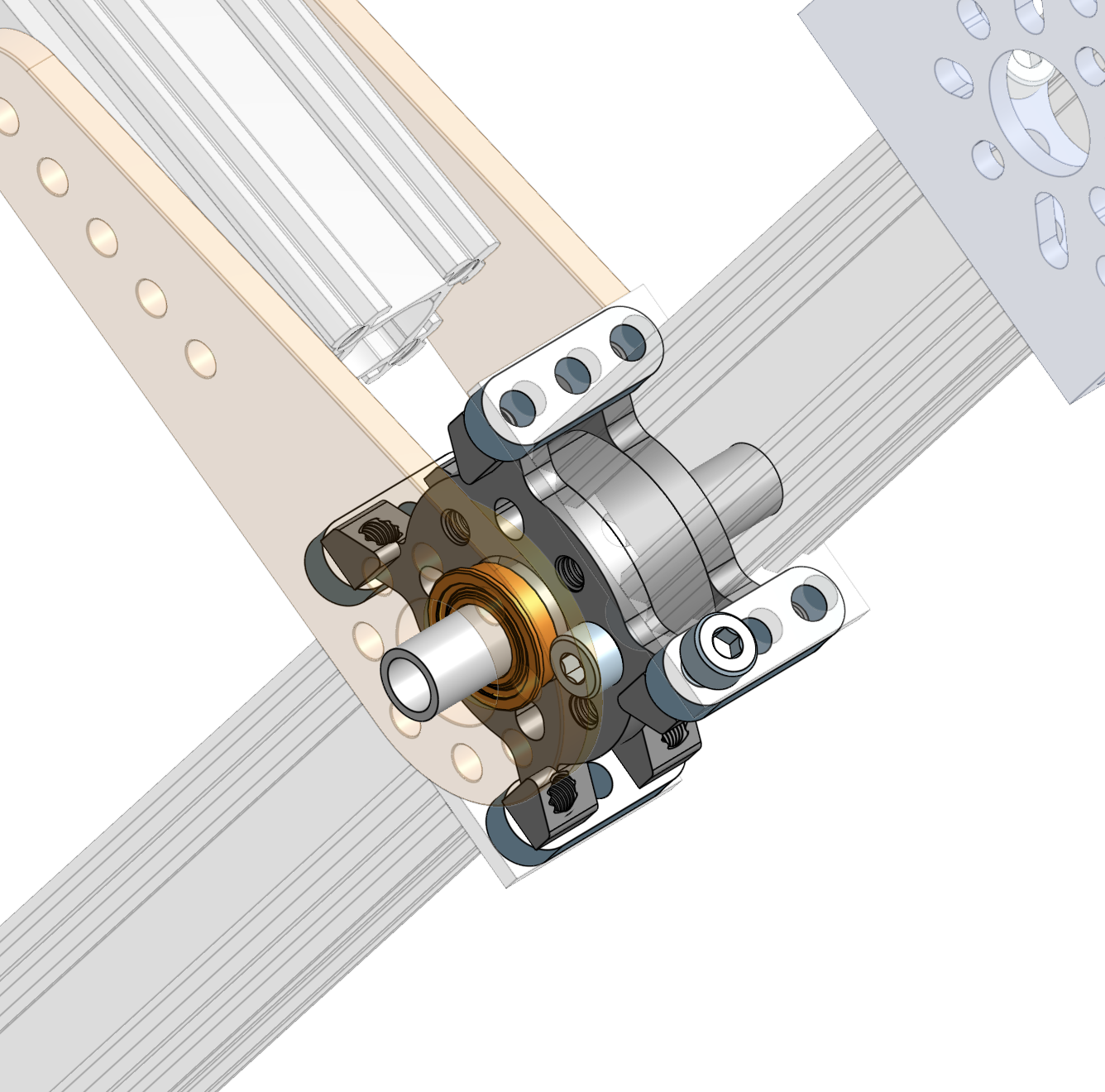 Photo creditmechanical/rocker_bogie/images/pivot_almost.png JPL / California Institute of Technology and Open Source Rover contributors · Apache-2.0Unmodified source image. |
|---|---|
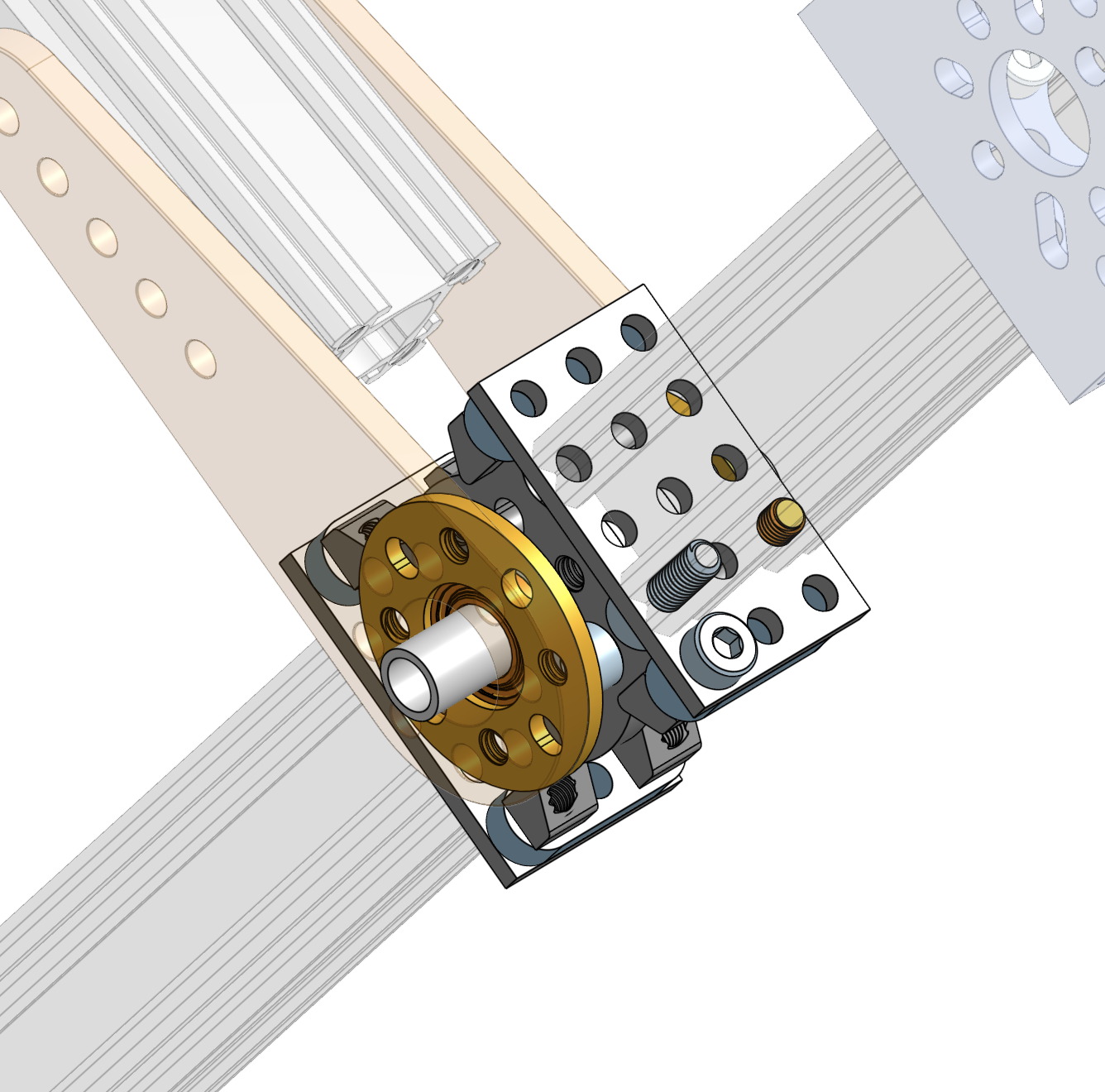 Photo creditmechanical/rocker_bogie/images/pivot_complete_inplace.png JPL / California Institute of Technology and Open Source Rover contributors · Apache-2.0Unmodified source image. | 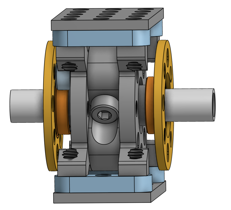 Photo creditmechanical/rocker_bogie/images/pivot_complete_side.png JPL / California Institute of Technology and Open Source Rover contributors · Apache-2.0Unmodified source image. |
Wait with the yellow and orange (ball bearing) parts. The bearing should first be inserted into the yellow hub.
Tip: Use the OnShape model and navigate to the tab 'rocker-bogie' in the bottom to isolate this assembly. Then right click on various parts to temporarily hide them so you can see how the assembly works in 3D.
Attach the control arms to the joint bearings
Referencing the orange and yellow parts in the image below, connect the hub (yellow) with the inserted bearing to the control arm using 8x socket or button M4 screws of length 12mm (or 10mm). Use washers so that the screw doesn't bury itself in the plastic control arm and to make sure the screw doesn't extend (much) on the insides of the hubs. When done, the bearing should not be able to fall out. Put these two assemblies aside for now. We'll connect each finished joint to the rockers in the following step.
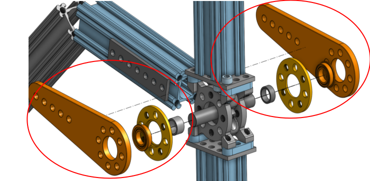
Photo credit
mechanical/rocker_bogie/images/exploded_view.png
JPL / California Institute of Technology and Open Source Rover contributors · Apache-2.0Unmodified source image.
Create the bogie
Attach a 3 hole x 5 hole plate 1116-0024-0040 to each of two length 96mm aluminum extrusions 1118-0024-0096 with 10mm button head screws as shown below. Pay attention to direction of the slits for the cabling. You'll want the slit to face the short side of the plate.
Now attach the plate to a 3-hole flat beam, and to the bogie joint, with 10mm socket head screws. You'll want the slits to face the top of the rover (the bogie arm) so you can route the cabling going to the front servo and motor inside of the channel.
| Plate on bogie shaft | Assembled bogie |
|---|---|
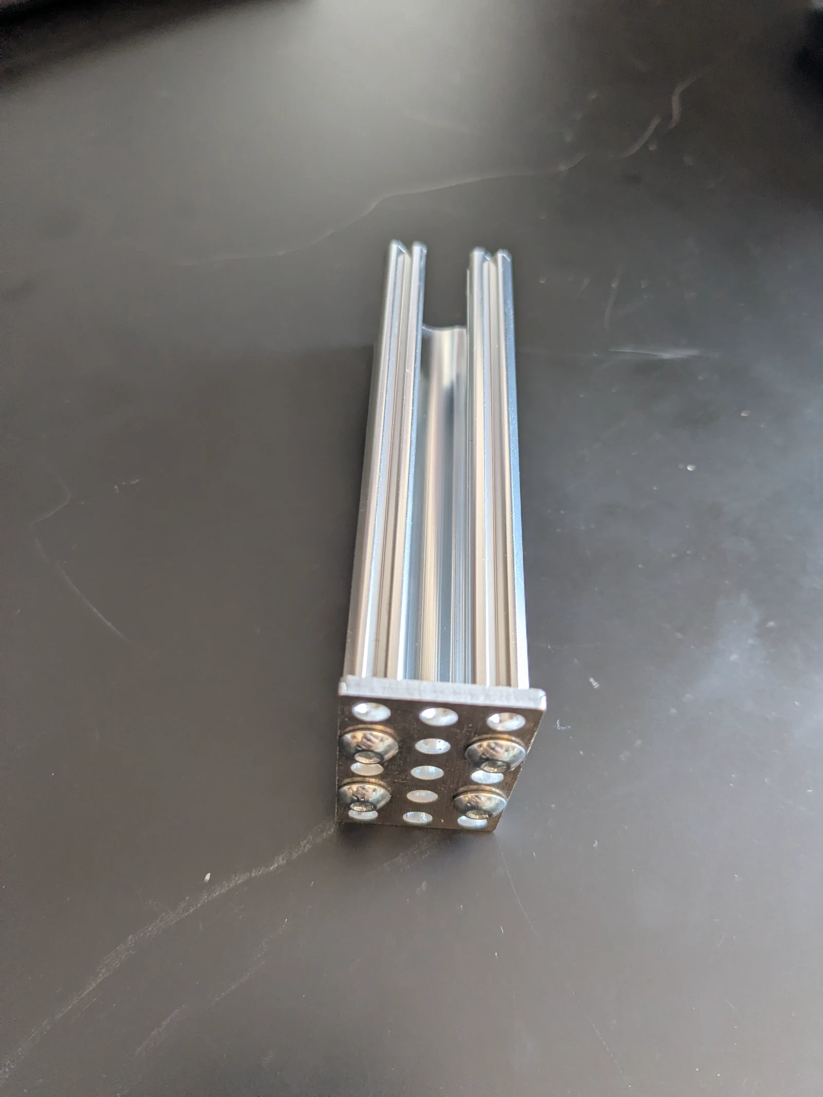 Photo creditmechanical/rocker_bogie/images/bogie_w_plate.jpg JPL / California Institute of Technology and Open Source Rover contributors · Apache-2.0Resized without cropping and converted to WebP. | 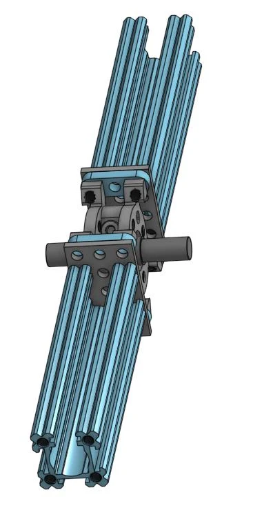 Photo creditmechanical/rocker_bogie/images/joints_assembled.jpg JPL / California Institute of Technology and Open Source Rover contributors · Apache-2.0Resized without cropping and converted to WebP. |
Attach the front servo bracket and middle wheel bracket
Attach bracket 1111-0003-0001 to the top of the extruded shaft you just attached to the joint using three or four M4 screws.
Attach U channel 1120-0002-0072 to the bottom of the other extruded shaft you just attached to the joint using three or four M4 screws.
Route wiring through bogie
Install 2911-0014-0001 grommets at the top and bottom of the extruded aluminum goRail (inside the U channel on the bottom, and inside the servo bracket on the top), to protect your wires as they go around corners.
Run the servo wiring, including a 54cm extension, down from the front servo, which should be near the front servo bracket, down toward the joint.
Run the 54cm encoder wires for the front corner motor from the front servo bracket toward the joint.
Run the middle motor power wiring from the U channel up toward the joint.
Run the middle motor encoder wires from the joint down to the U channel (or as shown in the picture, around it if you choose to notch your shafts), and encase in the protective sleeve.
It should look like the last picture below, except that your servo block and servo won't be installed at this point.
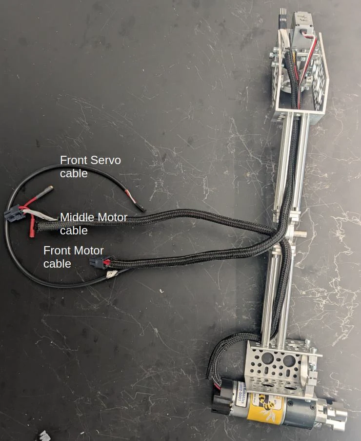 Photo creditmechanical/rocker_bogie/images/bogie_parts_step1.jpg JPL / California Institute of Technology and Open Source Rover contributors · Apache-2.0Resized without cropping and converted to WebP. |
|---|
| Bogie wiring installed. |
Attach the front servo and servo block
Attach bracket 1111-0003-0001 to the extruded shaft you just attached to the joint using three or four M4 screws.
Then assemble the servo block to the servo motor. Insert the set screw that came with the servo inside the hollow shaft that fits onto the spline profile on the servo output, but don't tighten it yet as we'll have to readjust later when calibrating the corner motors. This screw prevents the corner assembly from falling off the rocker-bogie while driving. Finally, attach the servo motor and block to the front rocker-bogie bracket. The image below shows the resulting assembly.
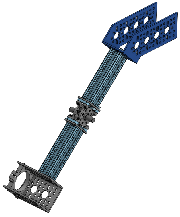 Photo creditmechanical/rocker_bogie/images/front_servo_to_rb.png JPL / California Institute of Technology and Open Source Rover contributors · Apache-2.0Unmodified source image. |
|---|
| Bracket and Bogie Joint |
Connect the control arms and rocker to the joint
Take one of the control arms (black plastic piece) with bearing and hub you made in an earlier step and attach the steel bracket, a goRail Nut (5 Hole), and 7x socket screws with washers like in the image.
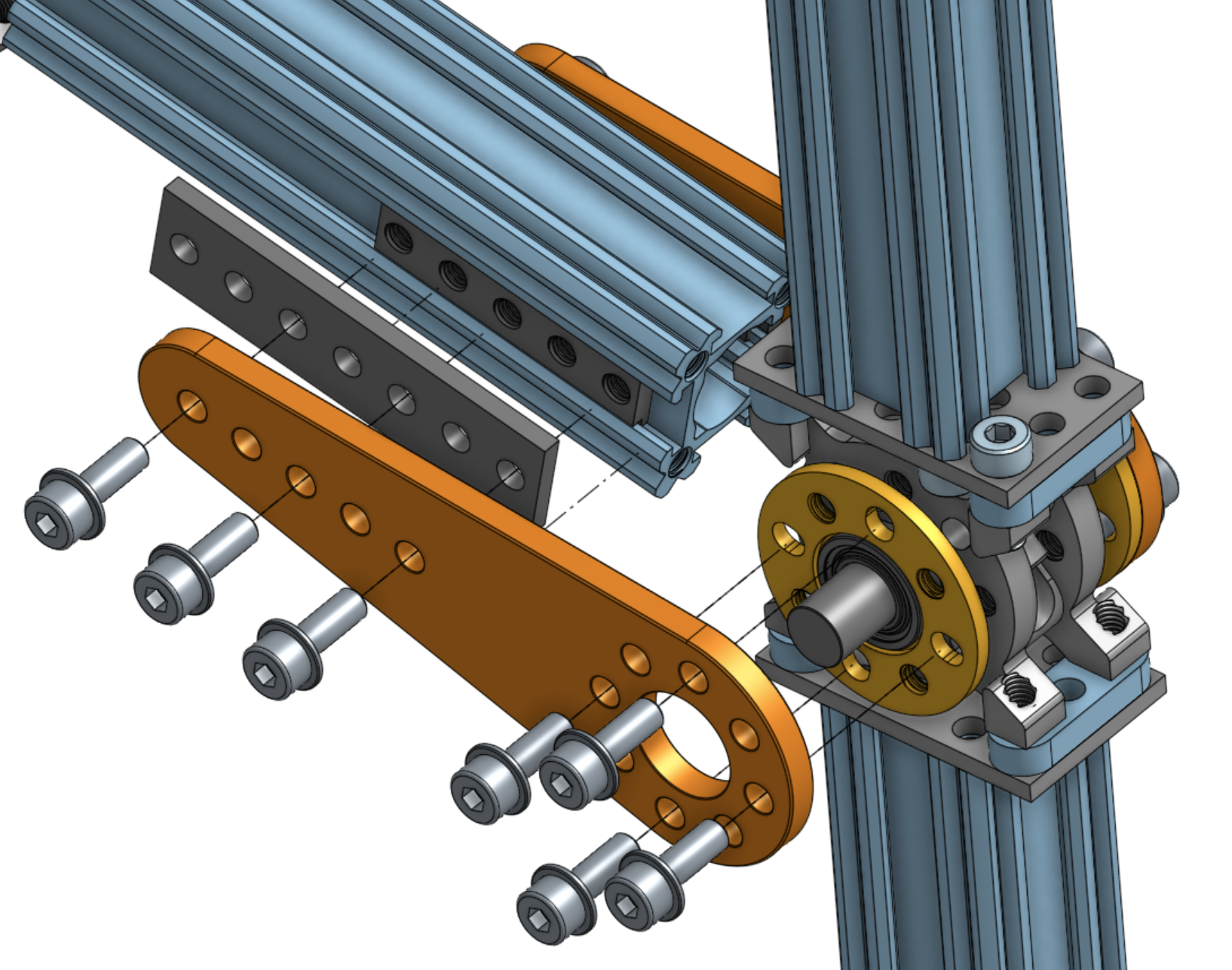
Photo credit
mechanical/rocker_bogie/images/rocker_extr_to_bogie_joint.png
JPL / California Institute of Technology and Open Source Rover contributors · Apache-2.0Unmodified source image.
[!NOTE] If you don't have the goRail nut (5 Hole) which was introduced July 2026, use three hurricane nuts instead. See the collapsed section below.
Instructions for when you don't have the goRail nuts
If the screws don't slide freely through the holes in the black control arm, drill the holes out to make sure the hurricane nuts rotate and lock in place in the rail.
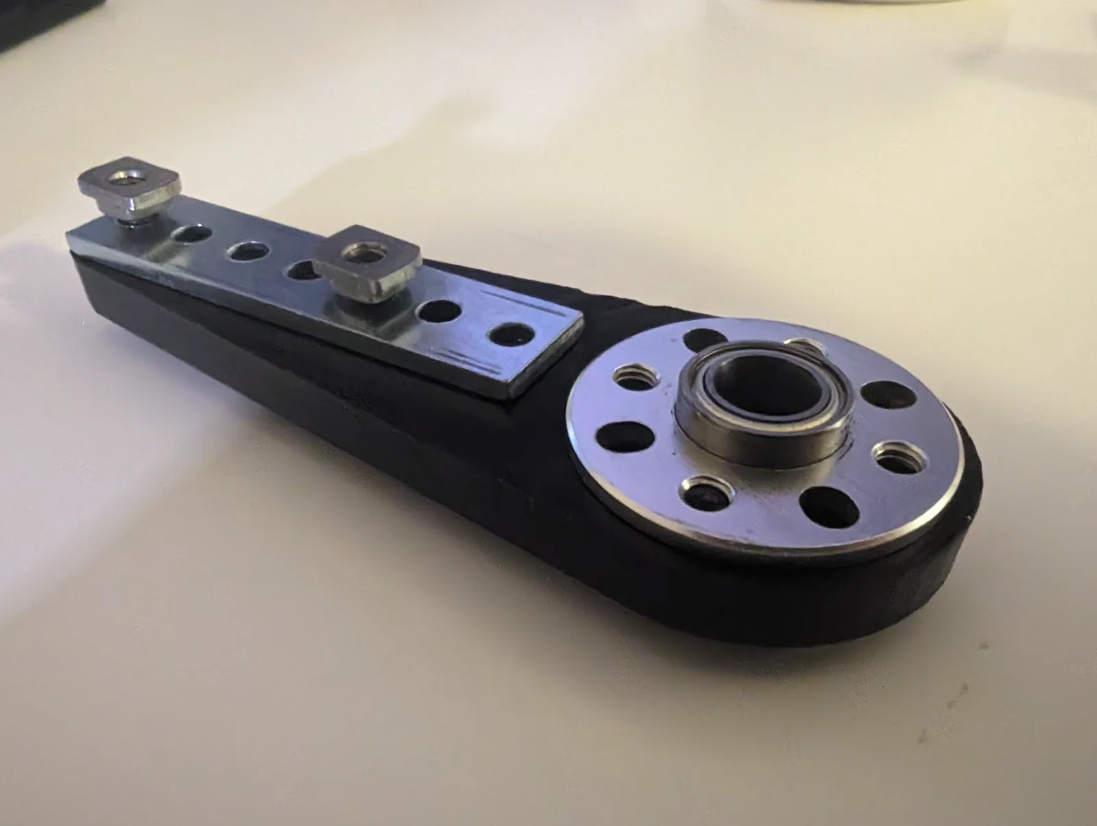
Photo credit
mechanical/rocker_bogie/images/control_arm_assembly.jpg
JPL / California Institute of Technology and Open Source Rover contributors · Apache-2.0Resized without cropping and converted to WebP.
Unlike the image, use 3 hurricane nuts instead of 2. Connect the short part of the rocker (shaft 1110-0024-00096) to the control arm on one side such that the hurricane nuts fit all the way in the channel. Tighten such that you can still slide the control arm relative to the channel. Make sure the slit faces the underside/back of the rover (you can also point the slit upwards or downwards if you prefer). The hurricane nuts have a tendency to seem stuck without actually getting their small 'wings' locked in the channel. If they're not properly inserted, the assembly will not have the required rigidity.
Repeat for the other control arm.
Route the wiring coming from the front, middle, and rear motors and servos through the slit (see left image below). It helps to temporarily keep the wiring in place with some tape as you attach the shaft to the bogie joint.
Flip the assembly over and repeat on the other side, making sure the setup is symmetric. Now tighten the screws all the way.
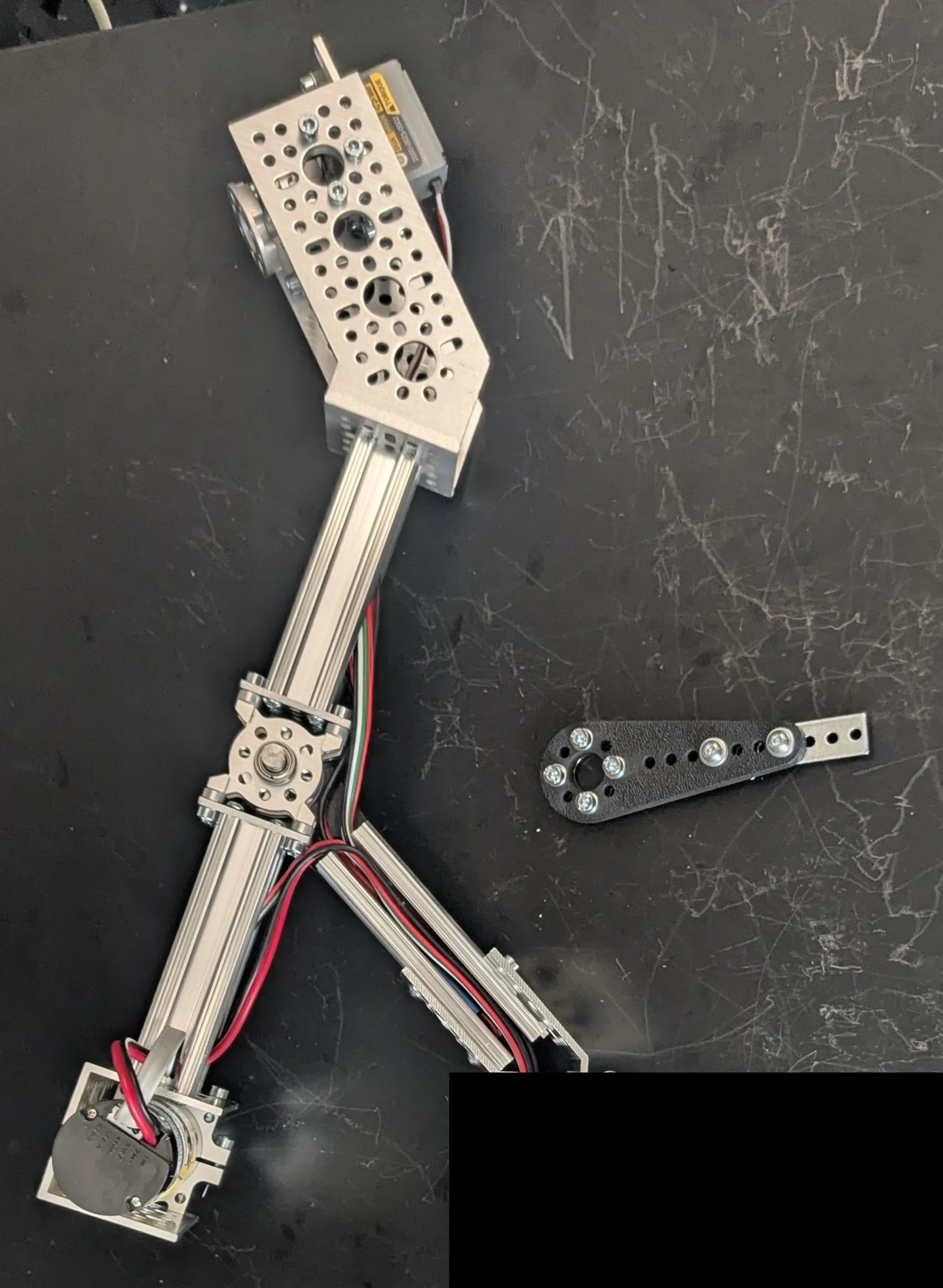 Photo creditmechanical/rocker_bogie/images/wiring_bogiejoint.jpg JPL / California Institute of Technology and Open Source Rover contributors · Apache-2.0Resized without cropping and converted to WebP. | 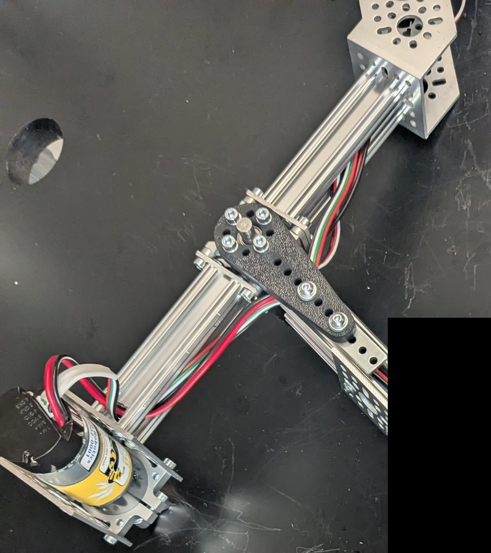 Photo creditmechanical/rocker_bogie/images/wiring_bogiejoint_done.jpg JPL / California Institute of Technology and Open Source Rover contributors · Apache-2.0Resized without cropping and converted to WebP. |
|---|---|
| Running wiring through short shaft of rocker | Joint installed. |
[!CAUTION] the OnShape model may represent the orientation of the slits incorrectly. In order to make the model nimble, the same rocker-bogie assembly is used on both sides of the rover which has the side-effect that the two assemblies aren't mirrored like they are supposed to be. Always stop to think about what you're building to avoid having to take things apart later.
Assemble the back servo
Attach the 1-channel U bracket to the long extruded shaft 11118-0024-0288 using 3 or 4 M4 socket screws of length 10mm. Assemble another servo block as you did before. Insert this into the 1-channel bracket and attach using 6 button M4 screws of length 10mm (6mm or 8mm also works).
Attach the front and back of the rocker-bogie
Use 4 hurricane nuts and the 45-degree bracket to connect the front and back of the rocker-bogie with 6mm M4 socket screws, as shown in the image below, on the underside of the rover. Avoid screws longer than 6mm, as they will hit the goRail before fully tightening.
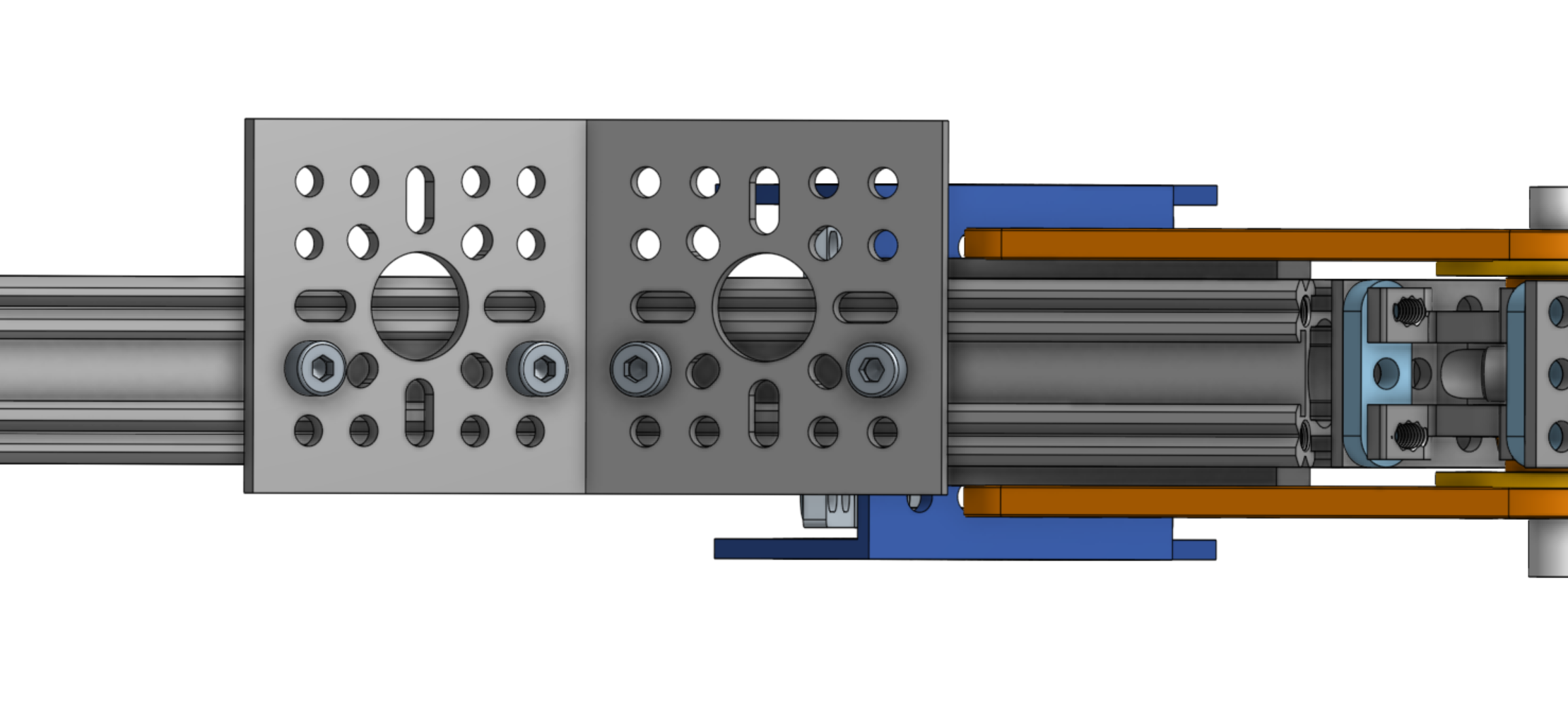
Photo credit
mechanical/rocker_bogie/images/connect45bracket.png
JPL / California Institute of Technology and Open Source Rover contributors · Apache-2.0Unmodified source image.
Flip the assembly over and attach the two brackets like in the picture below, using 4 more hurricane nuts and socket screws to secure the pieces to the rocker bogie aluminum extrusions. Then route all wires through the aluminum channel that will eventually slide into the rover body. The slit in the channel should orient in the direction where most of the cables enter it (flipped compared to the image below) but either direction works.
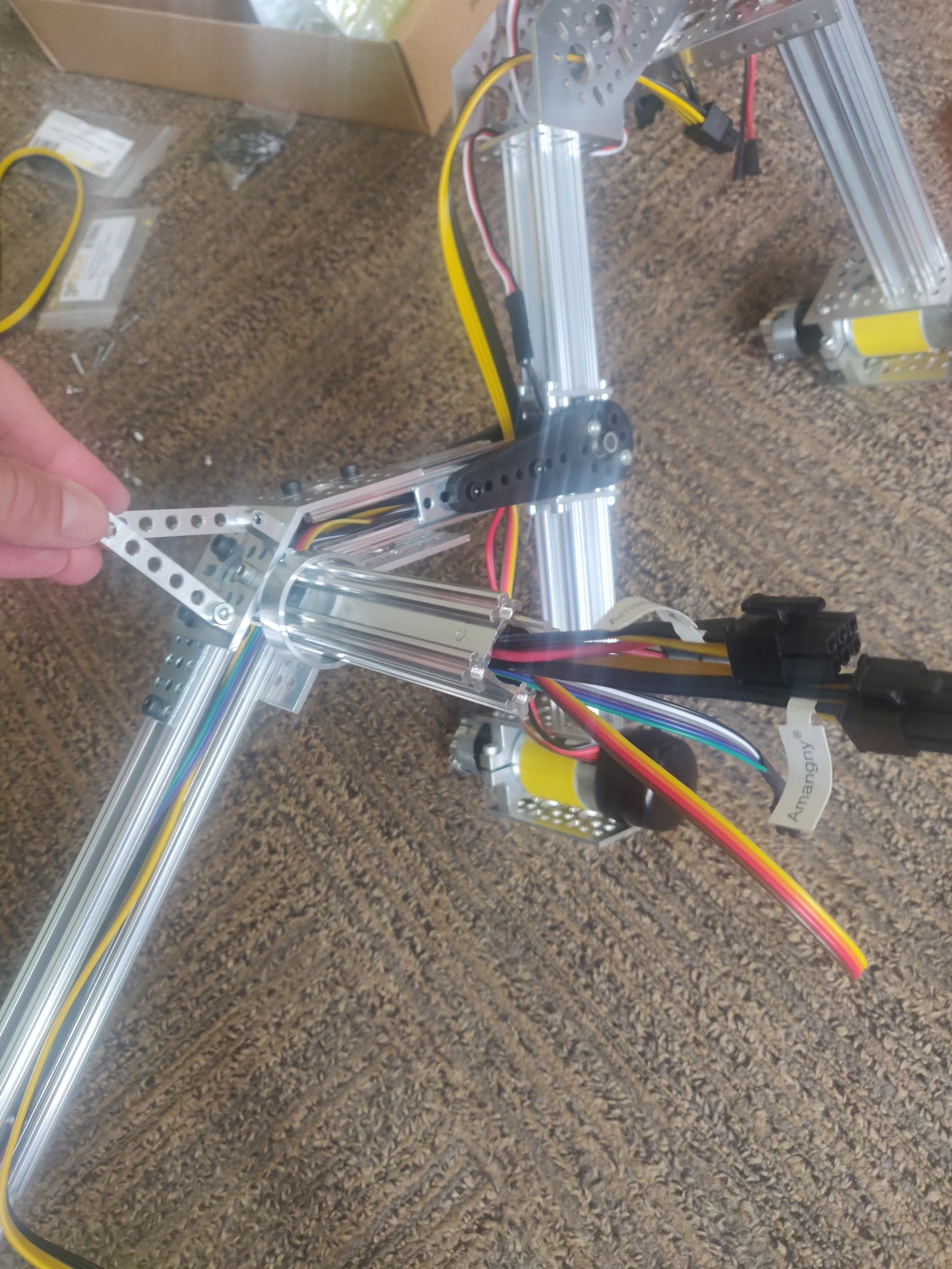 Photo creditmechanical/rocker_bogie/images/cabling-rocker-bogie.jpg JPL / California Institute of Technology and Open Source Rover contributors · Apache-2.0Resized without cropping and converted to WebP. |
|---|
| Wiring snugly fits inside the extruded aluminum channels, even with little or no sheathing. Only use this image as an idea of how the wiring should be routed, other parts of this image may not reflect the current state of the rocker-bogie at this stage in the process. |
Secure the channel to the rocker-bogie using 5 hurricane nuts (2 at the bottom) and socket screws, making sure the channel end sits flush to the other channels and the wiring isn't squeezed inbetween.
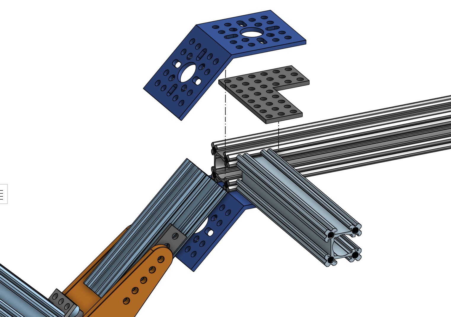 Photo creditmechanical/rocker_bogie/images/connect45topbracket.png JPL / California Institute of Technology and Open Source Rover contributors · Apache-2.0Unmodified source image. | 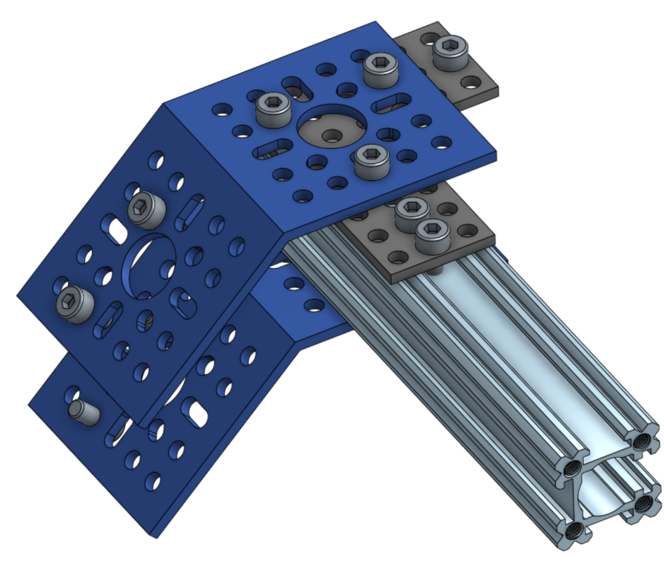 Photo creditmechanical/rocker_bogie/images/rocker-body-axis-screws.png JPL / California Institute of Technology and Open Source Rover contributors · Apache-2.0Unmodified source image. |
|---|
Repeat these steps for the other rocker-bogie, making sure it mirrors the first assembly. Once you're done, you're ready with these very important subassemblies!
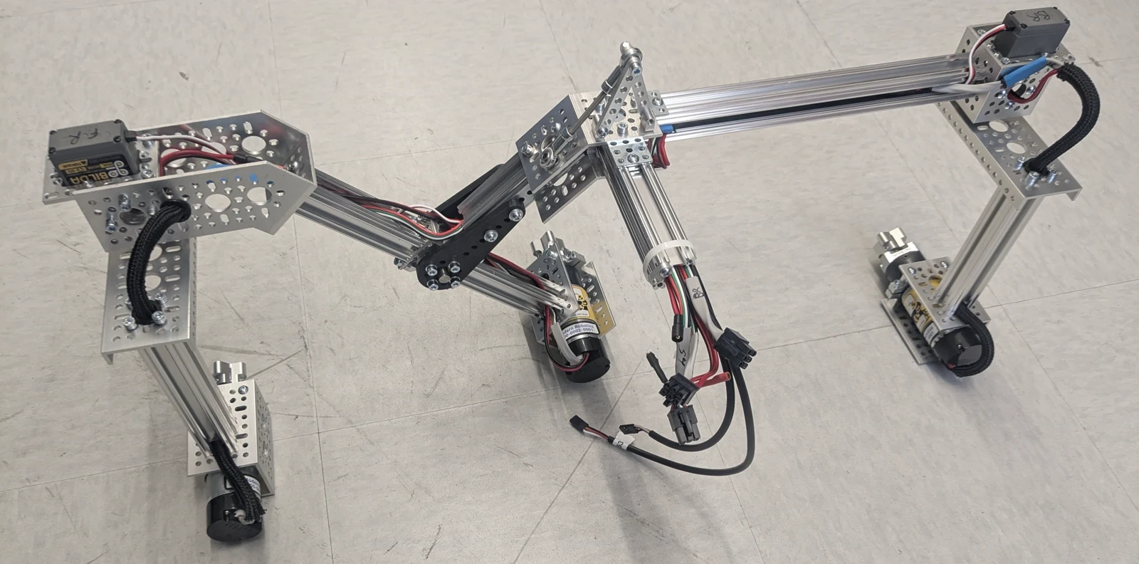
Photo credit
mechanical/rocker_bogie/images/rocker_bogie_assembled.jpg
JPL / California Institute of Technology and Open Source Rover contributors · Apache-2.0Resized without cropping and converted to WebP.
Help improve documentation! Please make an issue on Github when you spot something that's off or can be improved. Pull requests are even better! If you have a question, post in the #troubleshooting channel in our Slack group.
Servo Motor Gear Replacement
In some cases, when the rover experiences a sudden, sharp impact (like a crash into a hard object), the corner servo motors can fail. More specifically, a central shaft holding two of the gears in place has been known to shear. When this happens, the gears will not mesh as smoothly, and, when forced, this can cause gear teeth to deform and break off completely from the output gear (see below).
Photo credit
mechanical/images/servo_gearset_replacement/deformed_output_gear.jpg
JPL / California Institute of Technology and Open Source Rover contributors · Apache-2.0Resized without cropping and converted to WebP.
Photo credit
mechanical/images/servo_gearset_replacement/broken_output_gear.jpg
JPL / California Institute of Technology and Open Source Rover contributors · Apache-2.0Resized without cropping and converted to WebP.
This does not mean that the servo motor is useless. We can replace the gearset of the servo motor instead of purchasing a whole new motor.
GoBilda sells replacement gearsets for their servo motors, as well as replacement shafts. Be sure you have grease for the gears!
For the rest of this guide, references to "top", "bottom", "output gear", and "central shaft" are according to the following image:
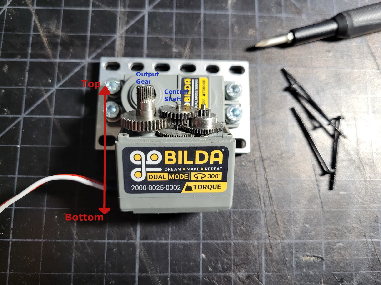
Photo credit
mechanical/images/servo_gearset_replacement/reference_gearset.jpg
JPL / California Institute of Technology and Open Source Rover contributors · Apache-2.0Resized without cropping and converted to WebP.
Diagnosing an issue
The first sign of an issue with the servo motors is when your corner wheels will not turn. This could be caused by either a loose electrical connection, or an issue in the gearset.
In either case, power down the rover to allow the servos to free spin. Verify that the electrical connections are stable before resorting to motor disassembly.
If your connections are stable, then manually rotate the corner assembly. Rotate it to the extremes slowly, going through this motion a few times. If at any point the gears feel like they are binding or sticking, then there is an issue in the gearset. At this point, it is possible that just the shaft has sheared and the gears themselves are still intact. If you hear any rattling or the binding isn't momentary, then at least one gear has likely been damaged and needs to be replaced.
If the gears bind up, do not force the rotation any further!! This could cause gears to fail if they haven't already!
Disassembling the Motor
-
You have a choice to either remove the motor from the corner assembly, or to disassemble the motor in-situ. In either case, first remove the screw connecting the servo hub-shaft to the servo output.
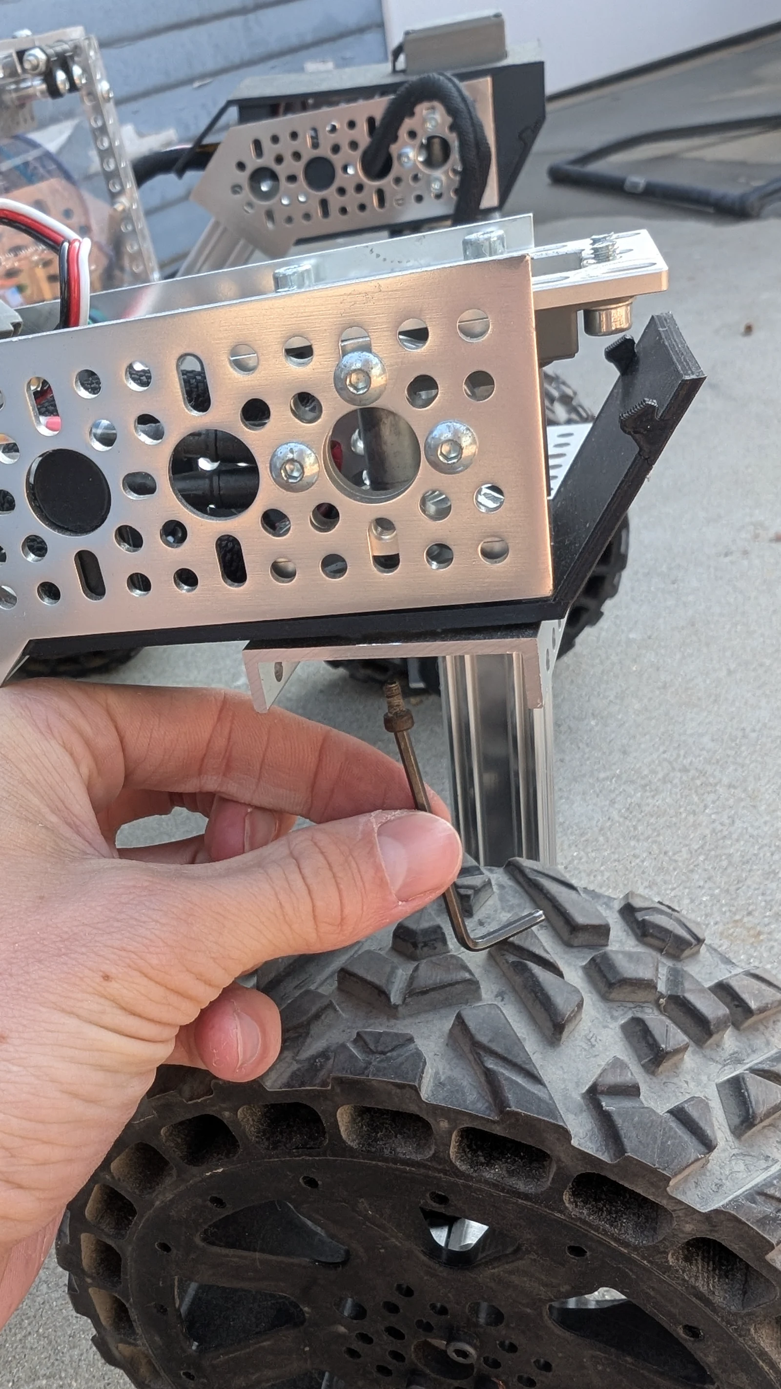
Photo credit
mechanical/images/servo_gearset_replacement/hub_shaft_disconnect.jpg
JPL / California Institute of Technology and Open Source Rover contributors · Apache-2.0Resized without cropping and converted to WebP.
-
Remove the corner screws from the servo motor body.
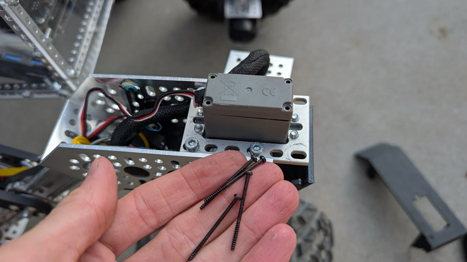
Photo credit
mechanical/images/servo_gearset_replacement/servo_screws.jpg
JPL / California Institute of Technology and Open Source Rover contributors · Apache-2.0Resized without cropping and converted to WebP.
-
Being careful not to remove the bottom portion of the body, which contains the servo circuit board, remove the body from the top portion of the servo.
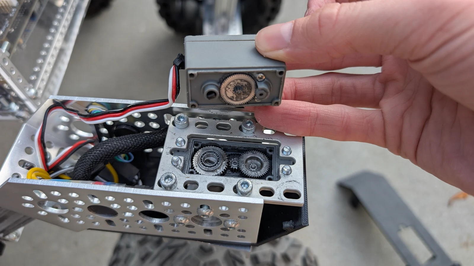
Photo credit
mechanical/images/servo_gearset_replacement/body_disassembly.jpg
JPL / California Institute of Technology and Open Source Rover contributors · Apache-2.0Resized without cropping and converted to WebP.
In the image, note how the shaft sections from the two central gears seem to have a ragged/jagged surface. This is the central shaft, which has sheared.
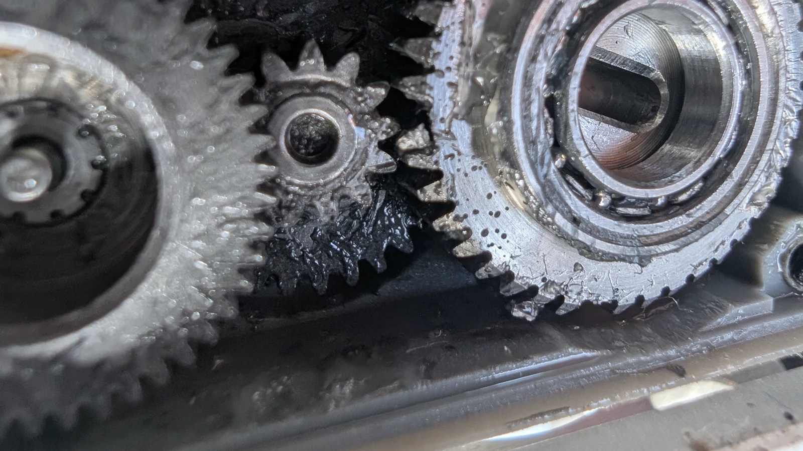
Photo credit
mechanical/images/servo_gearset_replacement/damaged_output_gear.jpg
JPL / California Institute of Technology and Open Source Rover contributors · Apache-2.0Resized without cropping and converted to WebP.
This closeup better shows both the sheared shaft, and the broken teeth on the output gear. In this case, both the output gear and the shaft need to be replaced
-
With a pair of tweezers or fine needlenose pliers, remove the gears from the motor housing.
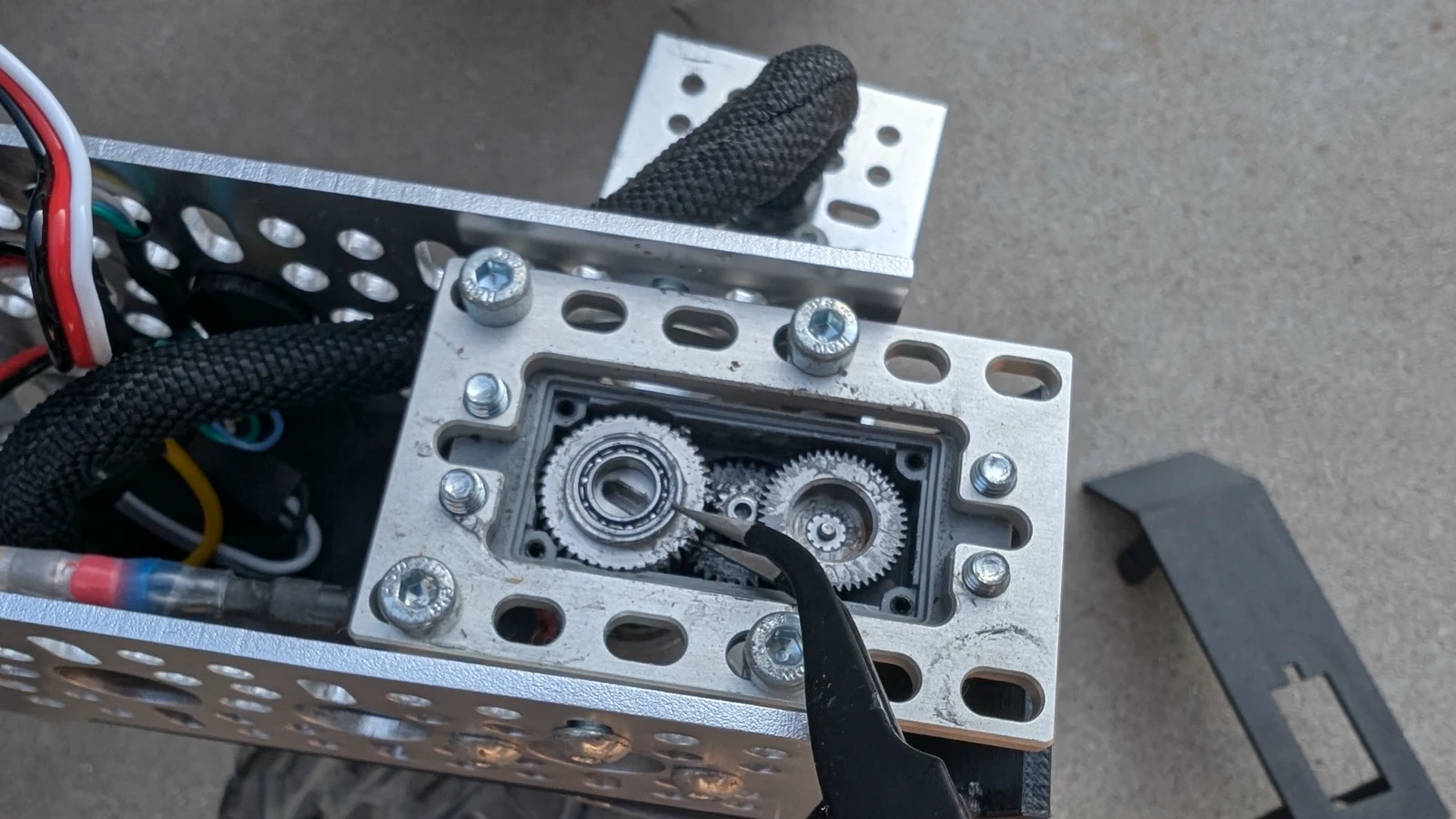
Photo credit
mechanical/images/servo_gearset_replacement/output_gear_removal.jpg
JPL / California Institute of Technology and Open Source Rover contributors · Apache-2.0Resized without cropping and converted to WebP.
-
Remove the top bearing from the output gear and place it on the new output gear. This bearing is not on the output gear in the replacement gearset from GoBilda, so it's important not to lose the original.
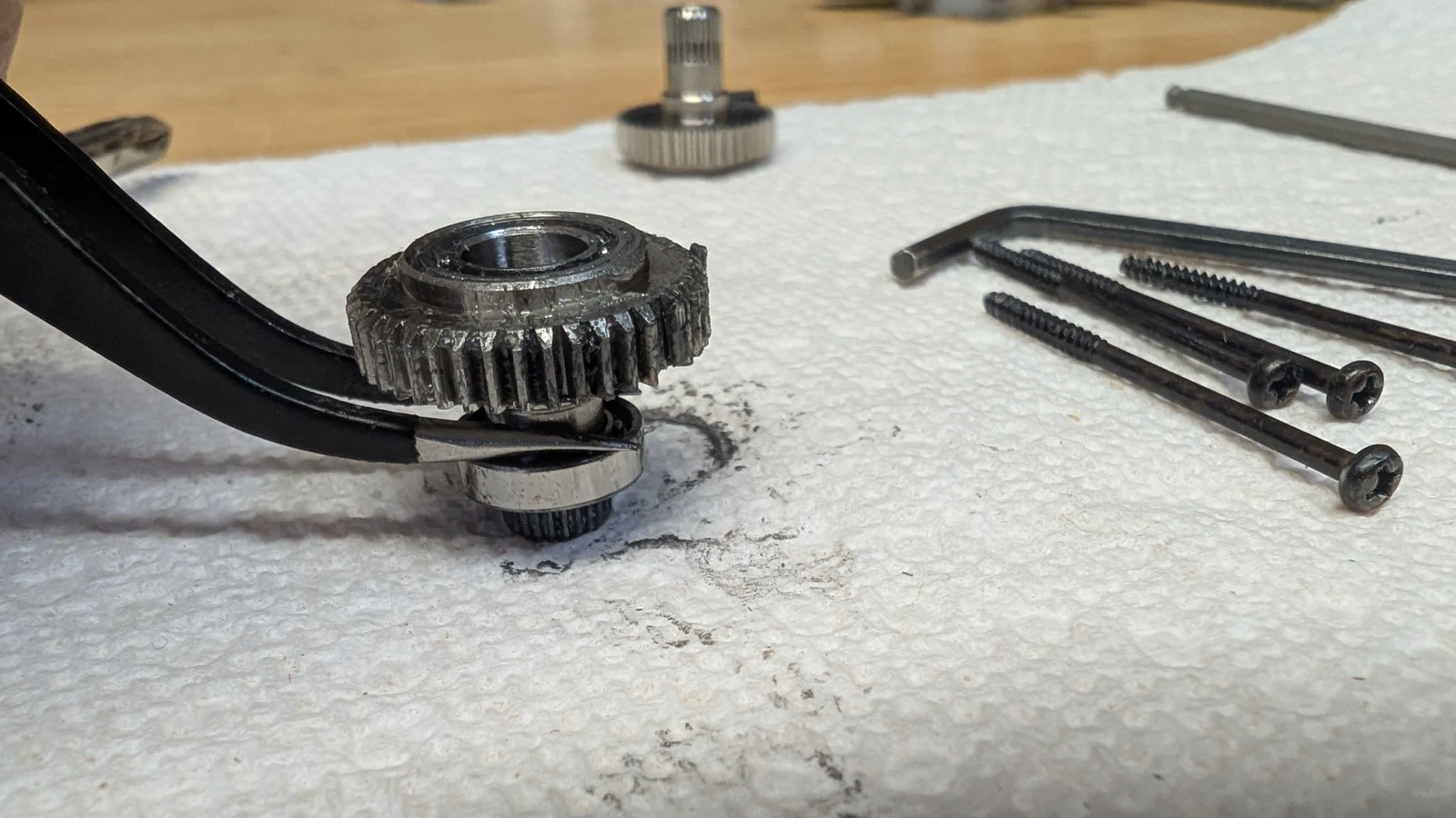
Photo credit
mechanical/images/servo_gearset_replacement/bearing_removal.jpg
JPL / California Institute of Technology and Open Source Rover contributors · Apache-2.0Resized without cropping and converted to WebP.
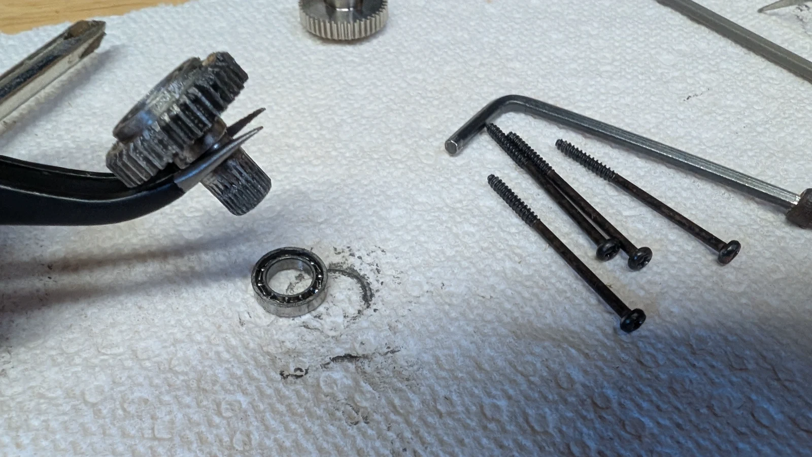
Photo credit
mechanical/images/servo_gearset_replacement/solo_bearing.jpg
JPL / California Institute of Technology and Open Source Rover contributors · Apache-2.0Resized without cropping and converted to WebP.
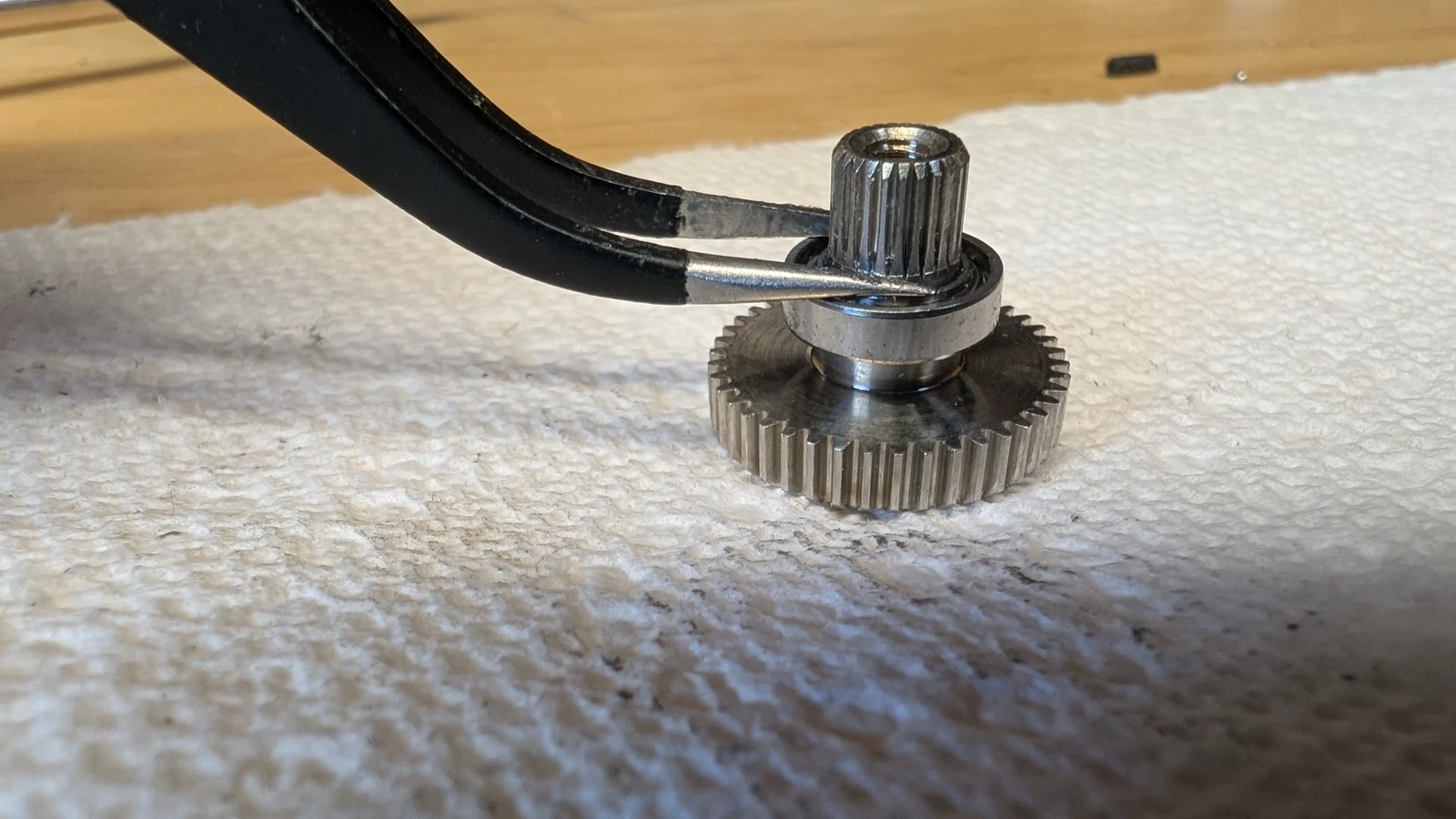
Photo credit
mechanical/images/servo_gearset_replacement/placed_bearing.jpg
JPL / California Institute of Technology and Open Source Rover contributors · Apache-2.0Resized without cropping and converted to WebP.
-
Place the output gear first, as the top bearing may interfere with placing the output gear later.
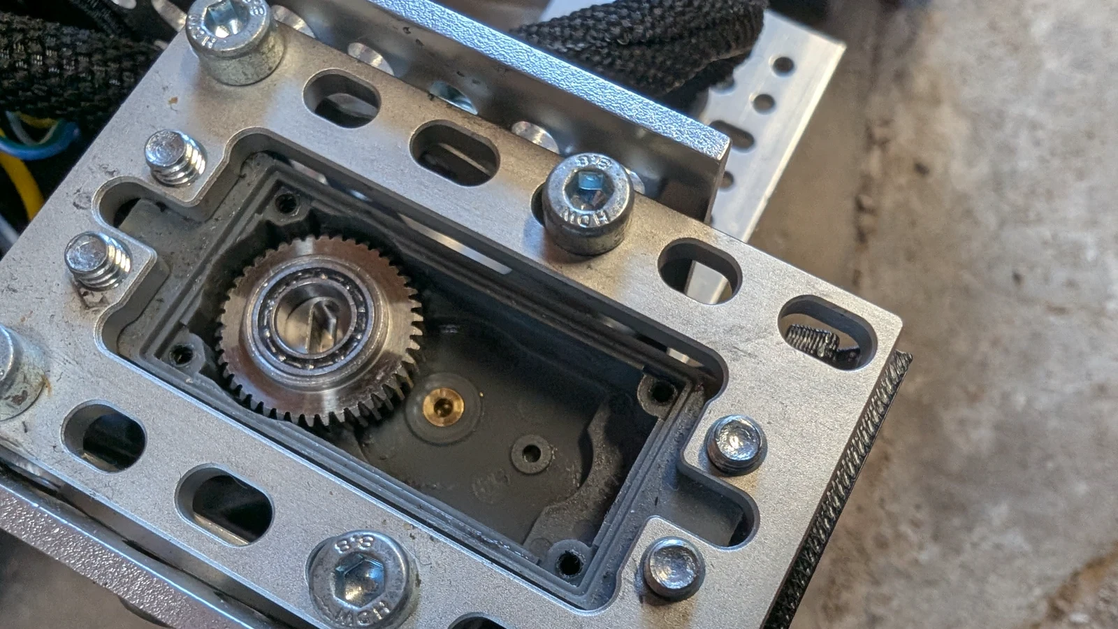
Photo credit
mechanical/images/servo_gearset_replacement/placed_output_gear.jpg
JPL / California Institute of Technology and Open Source Rover contributors · Apache-2.0Resized without cropping and converted to WebP.
-
While the other gears are out, remove the broken central shaft from both the top and bottom middle gears. Place the new central shaft in the top middle gear and replace in the case.
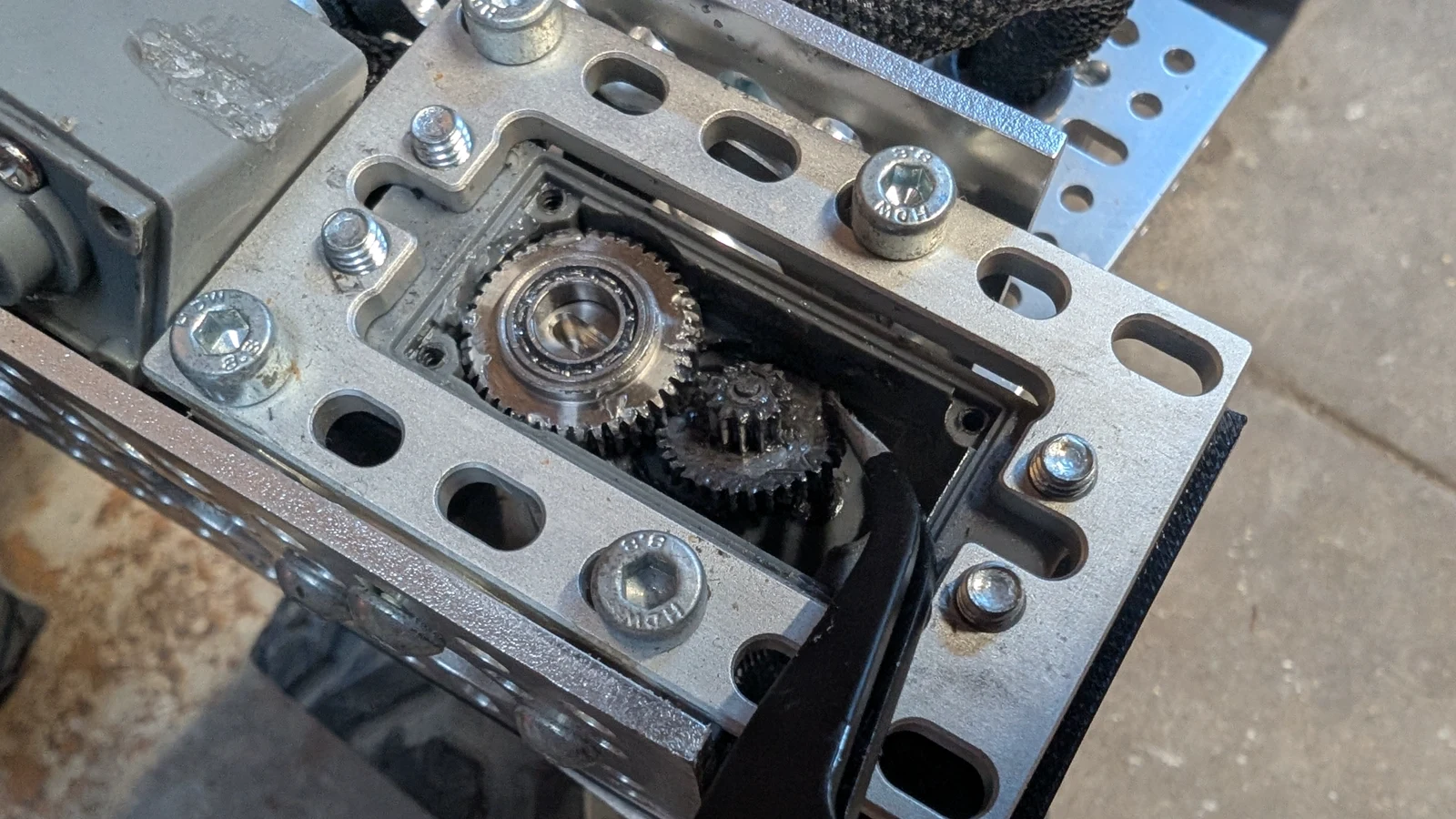
Photo credit
mechanical/images/servo_gearset_replacement/removing_shaft.jpg
JPL / California Institute of Technology and Open Source Rover contributors · Apache-2.0Resized without cropping and converted to WebP.
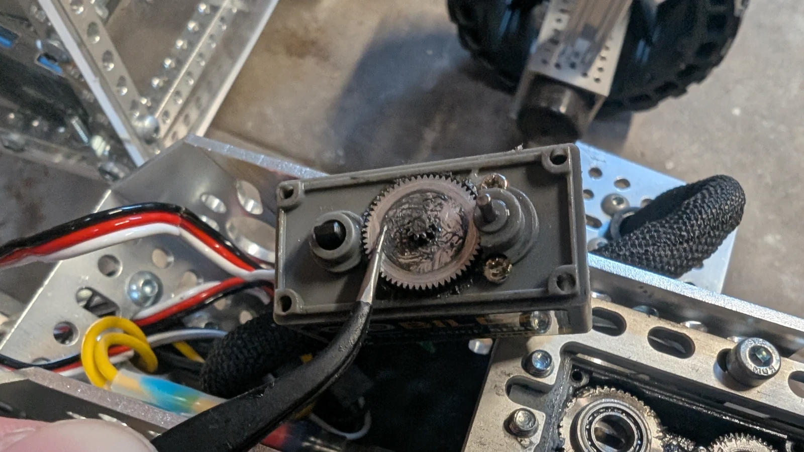
Photo credit
mechanical/images/servo_gearset_replacement/bottom_middle_gear.jpg
JPL / California Institute of Technology and Open Source Rover contributors · Apache-2.0Resized without cropping and converted to WebP.
-
With the new shaft installed in the top middle gear, place the two top gears in the case again. Make sure all the gears are meshing correctly.
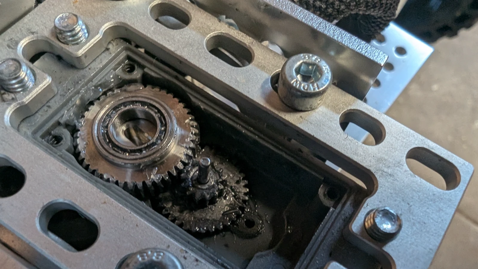
Photo credit
mechanical/images/servo_gearset_replacement/placed_middle_gear.jpg
JPL / California Institute of Technology and Open Source Rover contributors · Apache-2.0Resized without cropping and converted to WebP.
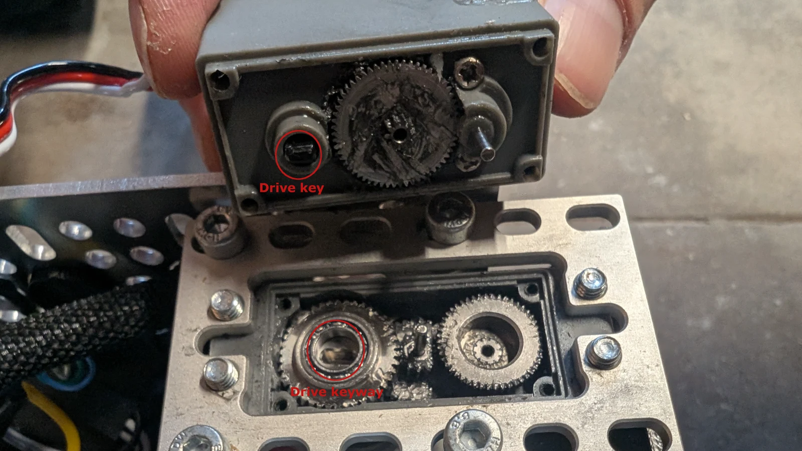
Photo credit
mechanical/images/servo_gearset_replacement/placed_gears.jpg
JPL / California Institute of Technology and Open Source Rover contributors · Apache-2.0Resized without cropping and converted to WebP.
-
Place a healthy dose of grease in the gears to ensure smooth operation.
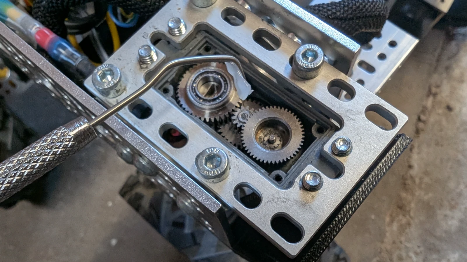
Photo credit
mechanical/images/servo_gearset_replacement/grease_1.jpg
JPL / California Institute of Technology and Open Source Rover contributors · Apache-2.0Resized without cropping and converted to WebP.
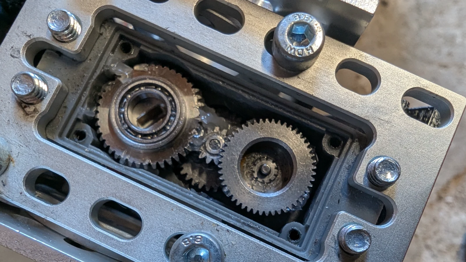
Photo credit
mechanical/images/servo_gearset_replacement/grease_2.jpg
JPL / California Institute of Technology and Open Source Rover contributors · Apache-2.0Resized without cropping and converted to WebP.
-
Reassemble the servo. Ensure that the black drive key is aligned with the keyway in the bottom of the output gear (see callouts in step 8).
Close up the servo body and screw in the body screws.
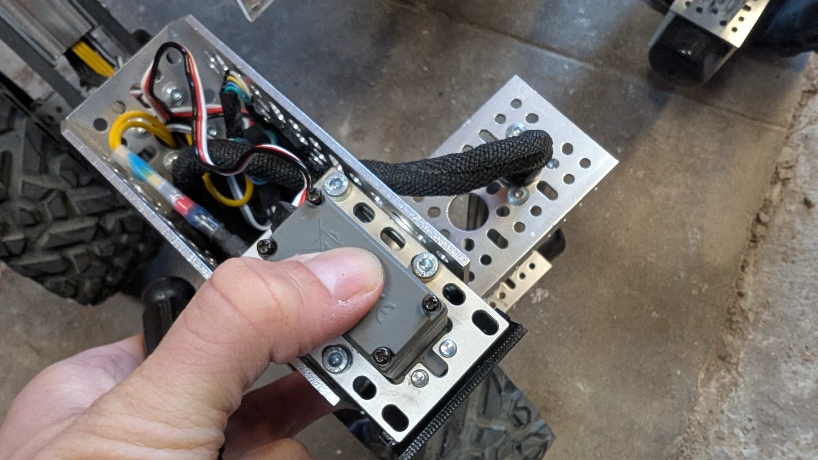
Photo credit
mechanical/images/servo_gearset_replacement/finishing_up.jpg
JPL / California Institute of Technology and Open Source Rover contributors · Apache-2.0Resized without cropping and converted to WebP.
-
If you unmounted the servo, remount the servo on the rover.
-
Recalibrate corner servo.
Mast Expansion
A mast can be added to the rover to house a camera, light, screen, environmental sensors or other components.
This section describes how to build the pan and tilt mast seen below. Before you get too far along it is recommended to attach two servos to the PCA board and write some basic code that confirms you can control them. This build information covers the mechanical parts of the build, installing the sensors and the code to integrate them is beyond the scope of these instructions.
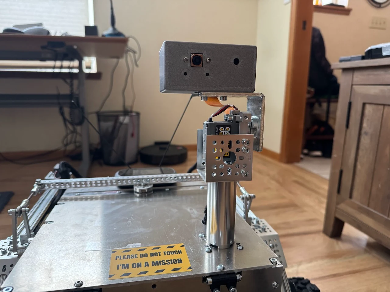
Photo credit
expansion/mast/images/scout-mast.jpeg
JPL / California Institute of Technology and Open Source Rover contributors · Apache-2.0Resized without cropping and converted to WebP.
Materials List
Mast Structure
The following materials are needed to build the main structure of the mast (as seen above). All parts were purchased from gobilda.com. The "head" of the mast is covered further down.
- torque servo (2000-0025-0002) x 2
- servo block (3217-2701-2501) x 2
- 72mm length goTube (4103-0032-0072) x 1
- steel angle bracket (1142-0001-0001) x 1
- 1 pack dual block mount (1205-0001-0005) x 1
- U-channel (1 hole) (1120-0001-0048) x 1
- Various M4 screws
- servo wire extension sets (either make your own or buy on GoBilda)
Head
- 3D printed "box" for the head. (STL files for these 3D parts are in the 3d_models folder)
- sensors! you need to put something on the mast (the build above holds a camera and there is an extra hole for a light)
Building It
Attach both of the servo blocks to the servos.
Underside
Remove the top plate of the rover body because you'll need to drill some holes in it. Drill a hole big enough for the servo hub shaft to fit through (exact size needed). In the example images this hole was placed 50mm back from the front and 50mm offset to the left (when facing the front of the rover). You'll also want to drill 4 holes to mount the block mount (would be good to know exact dimenions and locations for these holes).
Once the holes are drilled you can proceed with attaching the servo that controls the pan rotation to the underside of the body top plate as seen in the image below. You'll attach the servo with its block to the the block mounts and the block mounts to the top plate of the body.
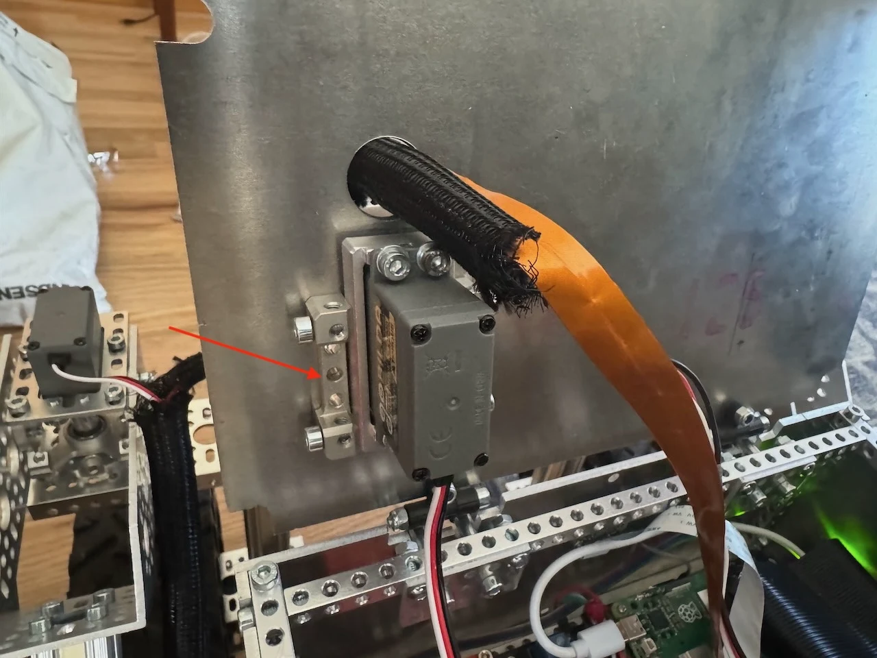
Photo credit
expansion/mast/images/pan-servo-attachment.jpeg
JPL / California Institute of Technology and Open Source Rover contributors · Apache-2.0Resized without cropping and converted to WebP.
Topside
Attach the goTube to the servo hub shaft from the top. Using a long hex driver down through the center of the goTube, attach this unit to the servo.
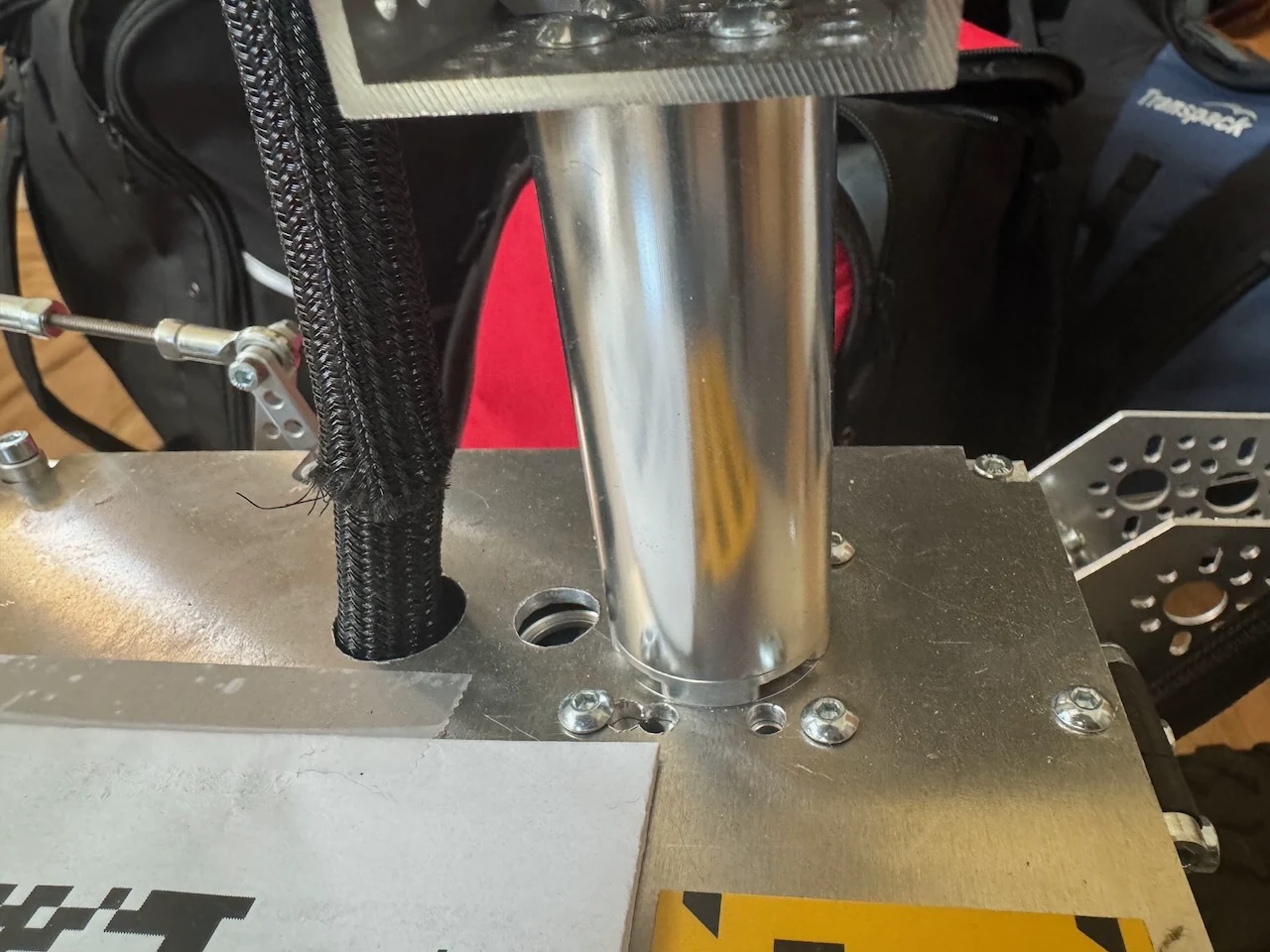
Photo credit
expansion/mast/images/mast-attachment-to-hub.jpeg
JPL / California Institute of Technology and Open Source Rover contributors · Apache-2.0Resized without cropping and converted to WebP.
Attach the second servo to the 1-hole U-Channel. Place the U-channel so that "U" is facing up. Attach this assembled part to the top of the goTube (the U-channel attached to the goTube is just visible in the image above). Attach the angle bracket to this second servo hub shaft – this will control the tilt of the head.
3D print the head and attach to the angle bracket.
Re-assemble the top plate to the rover body.
Original Build Downloads
Source and license
Original documentation: JPL / California Institute of Technology and Open Source Rover contributors. Reproduced under Apache-2.0. Individual image credits identify any separately licensed media. The full original copyright and permission notice is retained in that license file.
Republished the complete reviewed README and build chapters. Reformatted HTML as Markdown, resolved relative links, and served repository images locally. Photos resized without cropping; diagrams retain source resolution. Externally hosted or separately unverified media is linked at its original location. Introductory selection notes are by Meteor Makers; the original author is not responsible for those notes. Combined source chapters in build order and remapped chapter links to this page. Original build downloads are mirrored byte-for-byte; added a download index. Build animations retain every source frame.
Source revision: 0bea82401577. Retrieved 2026-10-03. This is a source snapshot, not a claim that the project was first published today or that its creator endorses Meteor Makers.